The question that comes up again and again
“We already have a separator on the system. Do we really need a coalescing filter as well?”
The answer, in almost every case, is yes — because separators and coalescers are designed for fundamentally different particle sizes. Understanding the distinction is the key to effective aerosol removal.
How aerosols form in compressed gas systems
Aerosols are not just “small droplets.” They are liquid particles so fine that they behave more like a gas than a liquid — they do not settle, they do not drain, and they pass through mechanical barriers that stop larger droplets.
In compressed gas systems, aerosols form through several mechanisms:
- Mechanical generation: Oil-lubricated compressors shear lubricating oil into sub-micron droplets during the compression cycle
- Condensation: As compressed gas cools (in aftercoolers, piping, receivers), water and hydrocarbon vapour condense into microscopic droplets
- Re-entrainment: Bulk liquid collected in separators and drains can be re-entrained as fine aerosol by high gas velocities
- Chemical processes: In electrolysers, acid mist generators, and chemical reactors, aerosols are a direct process byproduct
What separators do — and what they do not
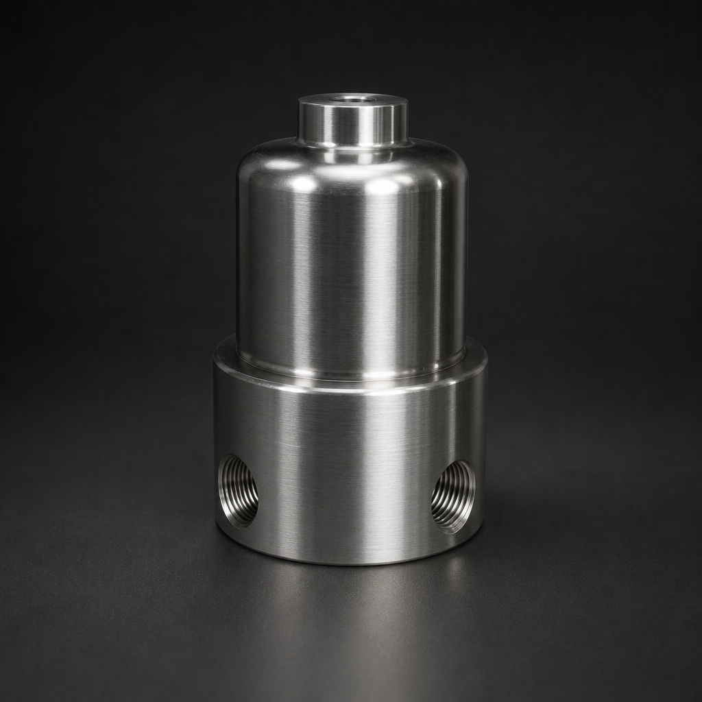
Bulk separators (also called moisture separators, cyclone separators, or demister vessels) use gravity, inertia, and centrifugal force to remove large liquid slugs and droplets. They are effective for:
- Liquid slugs and large droplets (> 10 µm)
- Bulk water after coolers and receivers
- Heavy condensate loads
The separator gap
Separators typically cannot capture droplets below 10 µm. Sub-micron aerosol — which constitutes the vast majority of oil mist from compressors — passes straight through. A separator removes perhaps 80% of the total liquid mass but only 10–20% of the total droplet count. The fine aerosol remains.
How coalescence actually works
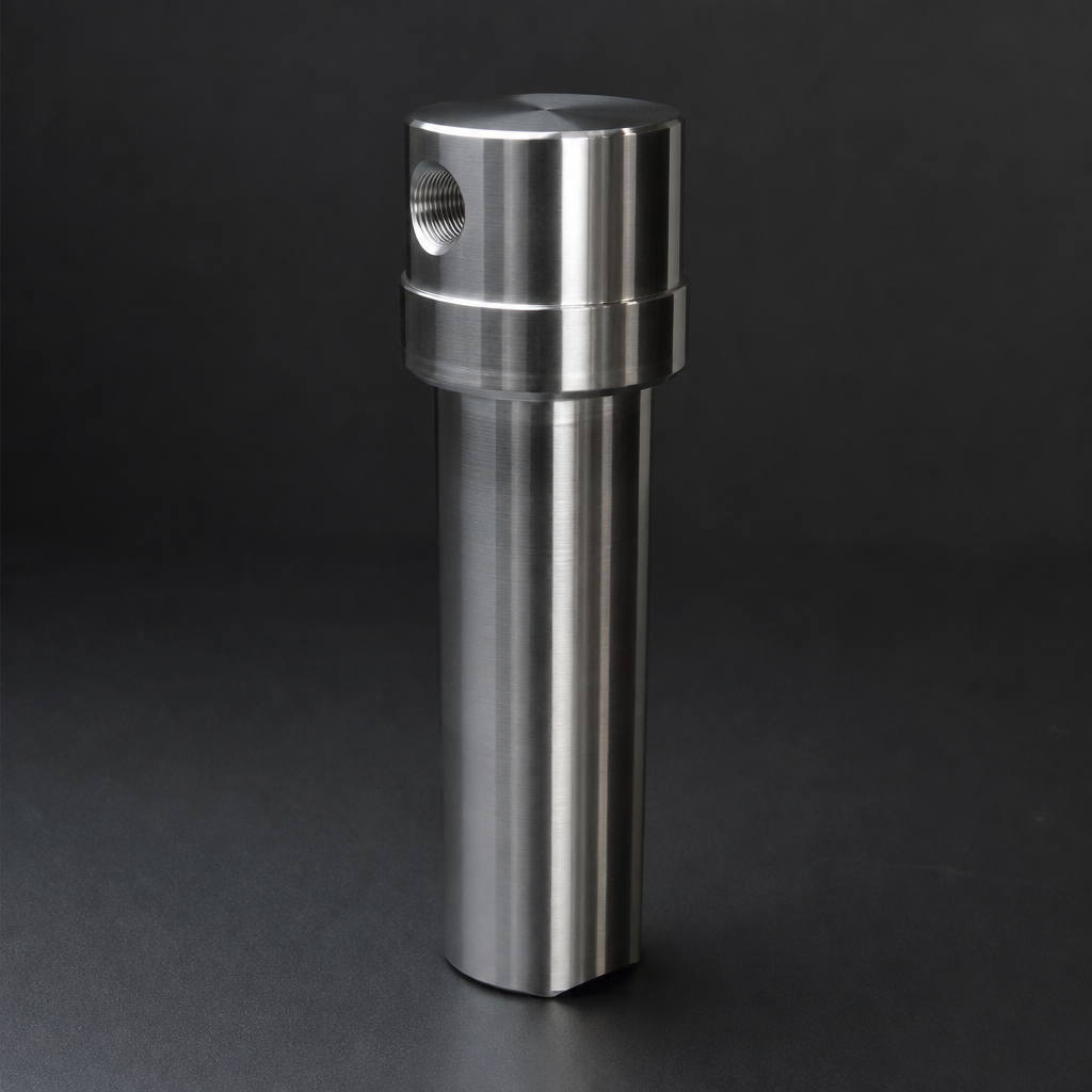
A coalescing element uses a fundamentally different mechanism. Instead of trying to separate liquid from gas by force, it allows the gas to pass through layers of progressively finer fibres that intercept, capture, and merge the tiny droplets.
Interception
Gas flows through the microfibre media. Sub-micron droplets, too small to settle, collide with the glass fibres by Brownian motion and inertial impaction.
Capture & coalescence
Captured droplets wet the fibre surface and merge with adjacent droplets, growing larger. Progressive media density encourages this merging process.
Drainage
Once droplets reach sufficient size (typically > 100 µm), gravity overcomes the gas drag. They drain down the element and collect in the housing sump.
Clean gas exits
The gas exits the element with residual oil content below 0.01 mg/m³ (Grade HE). An anti-reintrainment mesh prevents coalesced drops from being stripped back.
Separator vs. coalescer — side by side
| Parameter | Bulk Separator | Coalescing Filter |
|---|---|---|
| Mechanism | Gravity / inertia / centrifugal | Fibre interception + coalescence |
| Effective range | > 10 µm droplets | Down to 0.01 µm aerosol |
| Oil removal efficiency | Bulk liquid only | 99.99% at 0.1 µm (Grade HE) |
| Pressure drop | Very low (0.01–0.03 bar) | Low–moderate (0.05–0.10 bar clean) |
| Maintenance | Drain valve cleaning | Periodic element replacement |
| Position in system | First stage (upstream) | Second stage (downstream of separator) |
Why both stages are usually needed
In most industrial systems, a separator alone leaves sub-micron aerosol in the gas — and a coalescer alone may be overwhelmed by bulk liquid that should have been removed upstream.
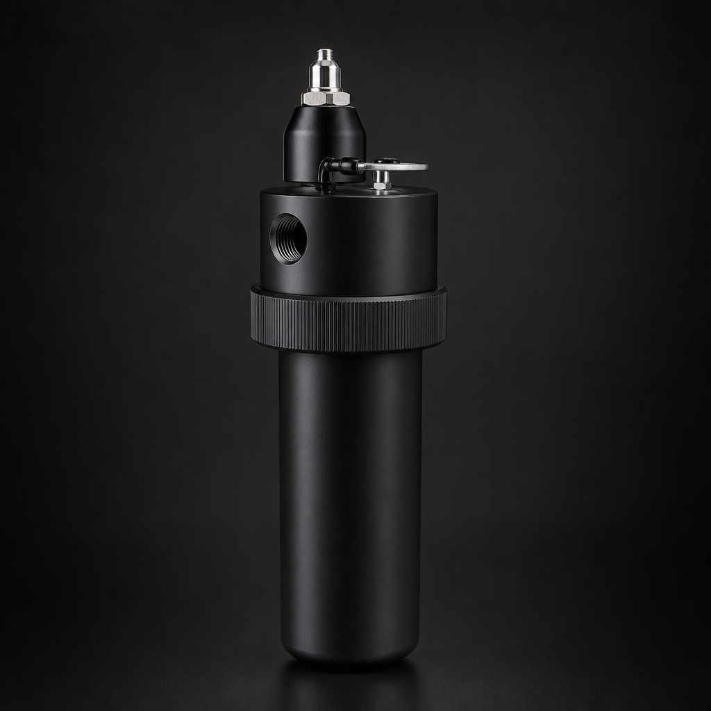
The correct two-stage approach
Stage 1: Bulk separator removes large liquid slugs, condensate, and coarse droplets. This protects the coalescing element from liquid flooding and extends its service life.
Stage 2: Coalescing filter removes the sub-micron aerosol that the separator cannot capture. This delivers the final gas quality needed by downstream equipment.
Flow direction matters
Coalescing elements have a defined flow direction — and installing them backwards destroys performance. Most inline coalescers flow outside-in: gas enters from the outside of the element and exits through the centre core. Coalesced liquid drains down the outside of the element to the housing sump.
Vacuum pump exhaust filters are the exception — they flow inside-out because the exhaust enters through the element core.
Never reverse flow direction
Reversing the flow through a coalescing element strips coalesced droplets off the drainage surface and re-entrains them into the clean gas. The filter appears to work (ΔP is normal) but delivers zero aerosol removal. Always check the flow arrow on the housing.
Key Takeaway
A separator and a coalescer do different jobs. Separators handle bulk liquid; coalescers handle sub-micron aerosol. Most systems need both, in sequence. If you have a separator and still see oil contamination downstream, the solution is almost certainly a coalescing filter — not a bigger separator.
Find the right coalescing filter for your system
Enter your flow rate and operating conditions — the Engineering Tool recommends the correct coalescing housing and element grade.