CNC routers and machining centres that use vacuum clamping tables are among the most demanding environments for vacuum pump reliability. Every time a workpiece is loaded, the pump draws air through the table — and with it, a cocktail of fine wood dust, MDF fibre, and, in wet-machining operations, coolant mist. Without proper filtration upstream and downstream of the pump, that contamination accumulates inside the pump body, degrades the oil, clogs internal passages, and ultimately causes premature failure. This guide explains the contamination risks specific to CNC vacuum clamping, the two-stage filtration strategy that protects the pump, and the R+F FilterElements products that make it practical.
Why CNC Vacuum Clamping Is Hard on Vacuum Pumps
Vacuum clamping works by holding a workpiece against a spoilboard or fixture through suction. The pump runs continuously — or cycles frequently — to maintain the required vacuum level, typically between 0.3 and 0.8 bar absolute. During that time, the pump is drawing air from the table surface, and that air is rarely clean.
The contamination profile depends on the material being cut:
- Solid wood and softwood: Coarse fibres and resin particles. Particle sizes range from a few microns to several hundred microns. Resin can polymerise on hot pump surfaces.
- MDF and particleboard: Ultra-fine dust with a median particle size often below 5 µm. MDF dust is hygroscopic and abrasive — a particularly damaging combination for rotary vane and claw pumps.
- Aluminium and composite panels: Metallic swarf and carbon or glass fibre fragments. These are hard and abrasive, and carbon fibre dust is electrically conductive.
- Wet-machining operations: Coolant mist and water vapour. Liquid carryover into a rotary vane pump dilutes the oil and causes corrosion; in oil-free claw pumps it can cause hydraulic lock.
Even a small amount of fine dust bypassing the pump inlet will accumulate over weeks of operation. The result is accelerated vane wear, increased oil change frequency, blocked oil separators, and — in the worst cases — seized pumps requiring full rebuild or replacement. A correctly specified CNC vacuum pump filter system prevents all of these failure modes.
The Two-Stage Filtration Strategy
Protecting a CNC vacuum pump requires two distinct filtration stages, each addressing a different contamination type and particle size range. A single filter is rarely sufficient.
Stage 1: Pre-Separator (Inlet Side)
The first stage is a coarse pre-separator or cyclonic separator installed as close to the vacuum table as practical. Its job is to remove the bulk of the dust load — particularly the larger particles above 10–20 µm — before the air reaches the fine filter. Without this stage, a fine filter element would blind rapidly, causing excessive pressure drop and reduced clamping force.
For woodworking and MDF applications, a cyclonic pre-separator is the preferred choice. It has no filter medium to replace and can handle high dust concentrations without pressure drop penalties. The separated dust falls into a collection bin that is emptied periodically.
Stage 2: Fine Inlet Filter
After the pre-separator, a fine particulate filter removes the sub-10 µm fraction that the cyclone cannot capture. This is the stage that protects the pump from the abrasive MDF dust that causes the most internal wear. The filter element must be rated for the full vacuum flow of the pump and must be capable of operating at the inlet vacuum level without collapsing.
For wet-machining applications, a coalescing element at this stage will also capture coolant mist droplets, preventing liquid carryover into the pump. The coalesced liquid drains to a collection bowl that is drained periodically.
Stage 3: Exhaust Oil-Mist Filter (Outlet Side)
Oil-sealed rotary vane pumps — the most common type used for CNC vacuum clamping — exhaust a fine oil mist with the discharge air. This mist is both a workplace air quality issue and a housekeeping problem. An exhaust oil-mist filter, fitted to the pump outlet, captures the oil aerosol and returns it to the pump sump via a drain line, or collects it in a bowl for disposal.
R+F FilterElements offers a complete range of vacuum pump exhaust filters designed specifically for this duty, with housings and elements matched to the pump's free-air delivery rating.
R+F FilterElements Products for CNC Vacuum Clamping
R+F FilterElements offers its own range of vacuum filtration housings and elements, engineered to European standards and available in configurations suited to CNC machining environments. Two housings are particularly well matched to this application.
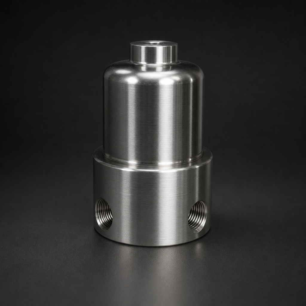
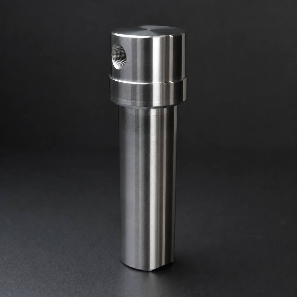
RF-H-433: Compact Vacuum Exhaust Filter
The RF-H-433 is a single-element vacuum pump exhaust filter housing in aluminium construction, designed for smaller CNC routers and single-spindle machining centres. It accepts RF-CS series vacuum-grade elements with a silica binder that resists the elevated temperatures found at pump exhausts — up to 200 °C — without shedding fibres into the discharge air.
The RF-H-433 is available with NBR seals as standard, with FKM/Viton seals available for applications where the pump oil has a high aromatic content. A bottom drain port allows collected oil to be returned to the pump sump via a sight-glass drain assembly.
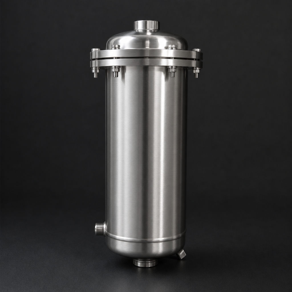
RF-H-437: Multi-Element Vacuum Exhaust Filter
For larger CNC machining centres, multi-spindle routers, or installations where several pumps share a common exhaust manifold, the RF-H-437 provides higher flow capacity in a multi-element configuration. The aluminium housing accepts up to four RF-CS elements in parallel, allowing flow rates that would overwhelm a single-element design without excessive pressure drop at the pump outlet.
Elevated back-pressure at the pump exhaust reduces pump efficiency and can cause overheating; the RF-H-437's multi-element design keeps differential pressure low even at maximum rated flow. The housing includes a differential pressure indicator port so that element condition can be monitored without interrupting production.
Technical Comparison
| Parameter | RF-H-433 | RF-H-437 |
|---|---|---|
| Housing material | Aluminium | Aluminium |
| Number of elements | 1 | Up to 4 |
| Max flow (free air) | Up to 100 m³/h | Up to 400 m³/h |
| Element type | RF-CS (vacuum-grade) | RF-CS (vacuum-grade) |
| Max element temperature | 200 °C | 200 °C |
| Seal options | NBR, FKM/Viton | NBR, FKM/Viton |
| Drain port | Yes (bottom) | Yes (bottom, per element) |
| Differential pressure port | Optional | Standard |
| Typical application | Single-spindle CNC router | Multi-spindle / shared manifold |
Omitting the pre-separator for MDF work:
Selecting the Right Inlet Filter
The inlet-side fine filter must be matched to the pump's maximum inlet flow and the vacuum level at which it operates. A filter housing designed for compressed air service is not suitable — the element must be rated to withstand the differential pressure without collapsing inward, and the housing must be leak-tight at sub-atmospheric pressures.
R+F FilterElements' vacuum filter range includes inlet-side housings with vacuum-rated elements. When specifying an inlet filter for a CNC vacuum clamping application, the following parameters should be confirmed:
- Pump free-air delivery (FAD): The filter must be rated for the pump's maximum FAD at the operating vacuum level, not just at atmospheric pressure.
- Dust load: MDF operations generate significantly higher dust concentrations than solid wood. A pre-separator is strongly recommended for any MDF application.
- Coolant mist: If wet machining is used, specify a coalescing element at the inlet stage. A particulate-only element will become saturated with liquid and block rapidly.
- Element change interval: In high-dust environments, plan for more frequent element changes. A differential pressure indicator on the inlet filter housing allows condition-based maintenance rather than fixed intervals.
Installation Best Practice
Correct installation is as important as correct product selection. The following guidelines apply to CNC vacuum clamping filtration systems:
Inlet Side
- Mount the pre-separator as close to the vacuum table as possible, before any long pipe runs. This minimises the distance over which dust-laden air travels and reduces the risk of dust settling in the pipework.
- Install the fine inlet filter immediately upstream of the pump, after the pre-separator. Allow sufficient straight pipe before the filter inlet to avoid turbulence affecting element performance.
- Ensure the filter housing drain is accessible and connected to a suitable collection point. A blocked drain will cause liquid to carry over into the pump.
- Use vacuum-rated flexible hose for connections to the pump to isolate vibration. Rigid connections can transmit pump vibration to the filter housing and loosen fittings over time.
Exhaust Side
- Mount the exhaust filter as close to the pump outlet as possible. Long exhaust pipe runs before the filter allow oil mist to condense on pipe walls and drip, creating a housekeeping problem.
- Ensure the drain line from the exhaust filter back to the pump sump is not kinked or blocked. A blocked drain causes oil to accumulate in the filter housing and eventually carry over into the exhaust air.
- Check the exhaust filter differential pressure regularly. A rising pressure drop indicates element saturation and the need for replacement. Ignoring this will increase back-pressure on the pump and reduce its efficiency.
Use our free Engineering Tool to get a filtration recommendation for your specific application in under 2 minutes.
Maintenance Schedule
A structured maintenance schedule prevents unplanned downtime and extends pump life. The following intervals are a starting point; actual intervals should be adjusted based on operating conditions and differential pressure readings.
| Maintenance Task | Interval (Light Duty) | Interval (Heavy MDF/Wet) |
|---|---|---|
| Empty pre-separator collection bin | Weekly | Daily |
| Check inlet filter differential pressure | Monthly | Weekly |
| Replace inlet filter element | Every 6 months | Every 1–3 months |
| Check exhaust filter differential pressure | Monthly | Weekly |
| Replace exhaust filter element (RF-CS) | Every 12 months | Every 3–6 months |
| Drain exhaust filter oil collection bowl | Monthly | Weekly |
| Check pump oil condition | Every 3 months | Monthly |
If the pump oil appears milky or discoloured, this is a sign that moisture or coolant mist is bypassing the inlet filter. Investigate the inlet filtration system before changing the oil — otherwise the problem will recur.
Common Mistakes to Avoid
Several recurring errors are seen in CNC vacuum clamping installations that lead to premature pump failure:
- Using a compressed air filter on the vacuum inlet: Compressed air filter elements are designed to withstand positive pressure from the outside. On a vacuum inlet, the pressure differential is reversed, and the element can collapse inward, blocking the pump inlet entirely.
- Omitting the pre-separator for MDF work: A fine filter alone will blind within days in a heavy MDF environment. The pre-separator is not optional for this application.
- Ignoring the exhaust filter drain: A blocked drain causes oil to back up into the element, saturating it and increasing back-pressure. The pump then runs hot and the oil degrades rapidly.
- Undersizing the exhaust filter: Specifying an exhaust filter based on nominal pump displacement rather than free-air delivery at operating vacuum leads to excessive pressure drop. Always size on FAD at the actual operating vacuum level.
- Delaying element changes: Filter elements are a low-cost consumable compared to a pump rebuild. Extending element life beyond the recommended interval to save money is a false economy.
Getting the Right Specification
Specifying a CNC vacuum clamping filtration system correctly requires knowing the pump model and its FAD at operating vacuum, the materials being machined, and whether wet machining is used. R+F FilterElements can assist with product selection for both the inlet and exhaust stages. Use the sizing wizard to generate a preliminary specification, or contact the team directly for a detailed recommendation based on your specific pump and application.
Replacement RF-CS elements for the RF-H-433 and RF-H-437 housings are held in stock for rapid despatch, minimising downtime when scheduled maintenance is due. All R+F FilterElements products are supplied with full documentation including element change instructions and disposal guidance for oil-saturated elements.
- Solid wood and softwood:
- Protecting a CNC vacuum pump requires two distinct filtration stages, each addressing a different contamination type and particle size range.
- R+F FilterElements offers its own range of vacuum filtration housings and elements, engineered to European standards and available in configurations suited to CNC machining environments.
- Pump free-air delivery (FAD):