
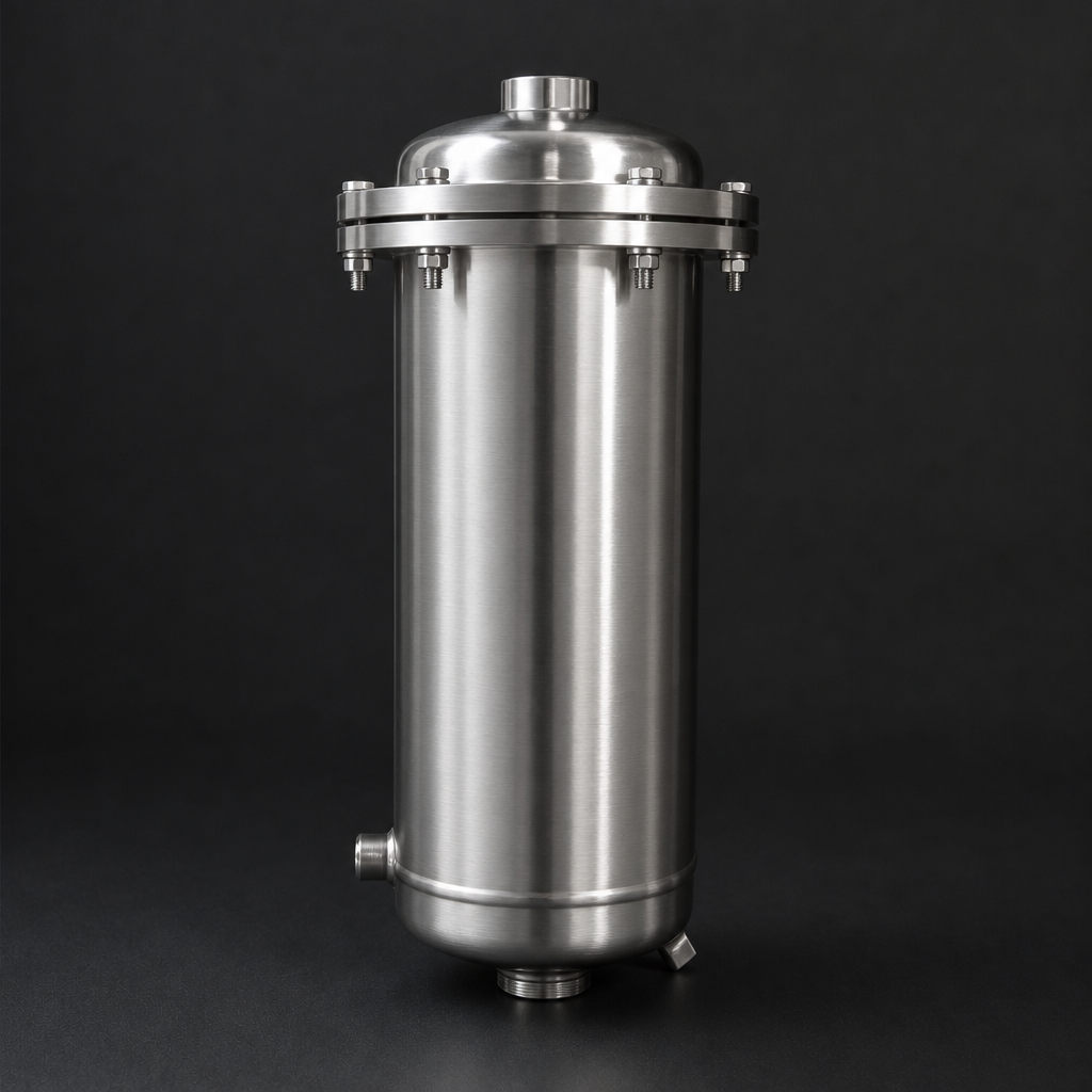
Large reciprocating compressors are workhorses of industrial gas processing, petrochemical plants, and power generation facilities. Yet one of their most persistent and underestimated problems is the oil mist and blow-by gas that escapes from the crankcase — contaminating the compressor room atmosphere, creating fire and health hazards, and accelerating wear on surrounding equipment. Proper compressor crankcase ventilation filtration is not optional; it is a fundamental engineering requirement.
What Is Crankcase Blow-By and Why Does It Matter?
In a reciprocating (piston) compressor, the piston rings are never a perfect seal. A small fraction of the compressed gas — along with oil vapour and fine oil mist — leaks past the rings into the crankcase on every stroke. This is known as blow-by. In a well-maintained machine, blow-by is modest. In an aged or heavily loaded compressor, it can be substantial — generating a continuous stream of oil-laden aerosols and hydrocarbon vapours that must go somewhere.
Without adequate crankcase ventilation filtration, the consequences are serious:
- Fire and explosion risk: Oil mist in air forms a flammable aerosol. Concentrations above the lower explosive limit (LEL) in a compressor room represent a genuine ignition hazard.
- Health exposure: Prolonged inhalation of oil mist aerosols is linked to respiratory irritation and, with mineral oils, potential carcinogenic exposure.
- Environmental non-compliance: Venting untreated crankcase emissions to atmosphere is increasingly restricted under industrial emissions regulations.
- Equipment contamination: Oil mist settles on electrical panels, instrumentation, and structural surfaces — causing corrosion and insulation breakdown.
How Coalescing Vent Filtration Solves the Problem
The engineering solution is a coalescing vent filter mounted directly on the crankcase breather port. The filter performs two functions simultaneously: it removes oil mist aerosols from the blow-by gas before it is vented, and it prevents the ingress of atmospheric dust and moisture back into the crankcase during the suction phase of the piston cycle.
Coalescing filtration works by passing the oil-laden gas through a borosilicate glass microfibre medium. The fine fibres intercept sub-micron oil droplets by diffusion and interception mechanisms, causing them to coalesce into larger droplets that drain by gravity into a sump. The cleaned gas exits through the outer face of the element. Efficiency of 99.99% at ≥ 0.1 µm is achievable with the correct element grade — critical for capturing the respirable fraction of oil mist.
For reciprocating compressor crankcase ventilation, R+F FilterElements offers its own range of coalescing vent filter housings from the RF-H-420 to RF-H-456 series, designed specifically for low-differential-pressure vent duty. These housings accept R+F branded RF-CS coalescing elements with silica binder construction — rated to 200 °C for applications where crankcase temperatures are elevated.
Sizing a Crankcase Vent Filter: Key Parameters
Correct sizing of a crankcase ventilation filter requires knowledge of several parameters that are often overlooked at the specification stage. The R+F Engineering Sizing Tool can assist with this calculation, but the following table summarises the key inputs and their typical ranges for reciprocating compressors:
| Parameter | Small Compressor (<75 kW) | Medium Compressor (75–250 kW) | Large Compressor (>250 kW) |
|---|---|---|---|
| Typical blow-by flow | 2–10 m³/h | 10–60 m³/h | 60–300 m³/h |
| Oil mist concentration | 20–80 mg/m³ | 50–150 mg/m³ | 100–300 mg/m³ |
| Recommended housing | RF-H-420 (1-element) | RF-H-435 (4-element) | RF-H-456 (16-element) |
| Element type | RF-CS (silica, 200 °C) | RF-CS (silica, 200 °C) | RF-CS (silica, 200 °C) |
| Drain connection | Manual drain | Auto float drain | Auto float drain + level alarm |
Industrial Emissions Directive (2010/75/EU):
Installation Considerations for Reciprocating Compressors
Mounting position and pipework design are critical to the performance of a crankcase vent filter. Several engineering principles apply:
Vertical Mounting and Gravity Drainage
The filter housing must be mounted vertically with the drain at the bottom. Coalesced oil must drain freely by gravity — any back-pressure on the drain will cause oil to re-entrain into the clean gas stream. For multi-element housings such as the RF-H-435 and RF-H-456, an automatic float drain is strongly recommended to prevent sump flooding during high-load operation.
Breather Pipe Sizing
The connecting pipework between the crankcase breather port and the filter inlet must be sized to keep gas velocity below 3 m/s. High velocity causes turbulent re-entrainment of oil droplets that have already separated in the crankcase. A short, straight run with minimal bends is ideal. Where long runs are unavoidable, a pre-separator pot upstream of the filter housing will reduce the liquid load on the coalescing element and extend service life.
Differential Pressure Monitoring
A differential pressure gauge or switch across the filter element is essential for maintenance scheduling. As the element loads with coalesced oil and particulate, differential pressure rises. For crankcase vent duty, a typical change-out interval is 2,000–4,000 operating hours, but this varies significantly with oil consumption and blow-by severity. Monitoring ΔP directly is more reliable than time-based replacement. The RF-CS element range is available in multiple sizes to match the RF-H-420 to RF-H-456 housing series.
Use our free Engineering Tool to get a filtration recommendation for your specific application in under 2 minutes.
Regulatory and Safety Context
European industrial facilities operating reciprocating compressors must consider several regulatory frameworks when designing crankcase ventilation systems:
- ATEX Directive (2014/34/EU): If the compressor room is classified as a hazardous area (Zone 1 or Zone 2), all electrical components of the ventilation system — including drain solenoids and ΔP switches — must be ATEX-rated.
- Industrial Emissions Directive (2010/75/EU): Crankcase emissions may be subject to VOC emission limits at permitted installations. Coalescing filtration alone may not be sufficient if the blow-by gas contains significant light hydrocarbon fractions — an activated carbon adsorber stage (RF-AC element or RF-DIA inline adsorber) downstream of the coalescer may be required.
- Occupational exposure: EN 481 and EN 689 govern workplace measurement and assessment of oil mist. Compliance requires demonstrating that time-weighted average (TWA) concentrations remain below the applicable OEL.
Selecting the Right R+F Solution
R+F FilterElements offers a complete range of vent and exhaust filter housings suitable for reciprocating compressor crankcase ventilation. The RF-H-420 to RF-H-456 series covers flow rates from 5 m³/h to 765 m³/h (free air delivery), with aluminium or 316L stainless steel construction depending on the chemical compatibility requirements of the blow-by gas.
For applications where the blow-by gas contains H₂S or other aggressive species, R+F branded RF-CS K-type elements (sour gas grade) are available. Where ultra-fine oil mist removal is required to meet strict environmental discharge limits, the RF-C coalescing element in the 51476 size achieves residual oil aerosol concentrations below 0.01 mg/m³ — well within the most stringent regulatory thresholds.
For guidance on selecting the correct housing size and element grade for your specific compressor, use the R+F Engineering Sizing Tool or contact our technical team directly.
- Fire and explosion risk:
- coalescing vent filter
- Correct sizing of a crankcase ventilation filter requires knowledge of several parameters that are often overlooked at the specification stage.
- Mounting position and pipework design are critical to the performance of a crankcase vent filter.
Related Reading
- Coalescing vs Particulate Filter Elements — Which Do You Need?
- Crankcase Ventilation Filtration — Engineering Principles
- ISO 8573-1 Compressed Air Quality — A Practical Guide
Try our Engineering Sizing Tool → or discuss your requirements with our technical team.

