Condensate is one of the most underestimated threats to a compressed air system. Every time atmospheric air is compressed, the water vapour it carries is concentrated — and as that air cools downstream, that moisture condenses into liquid water. Left unmanaged, condensate floods filter housings, degrades lubricants, corrodes pipework, and ultimately destroys the very filter elements designed to protect your process. Effective compressed air condensate management is not an optional extra; it is a fundamental requirement for reliable, efficient operation.
This guide explains how condensate forms, why drain selection matters as much as filter selection, and how R+F FilterElements' RF-H series — including float-drain variants — keeps your system dry and your filters performing as specified.
How Condensate Forms in a Compressed Air System
Atmospheric air at 20 °C and 60 % relative humidity contains roughly 10 g of water vapour per cubic metre. Compress that air to 7 bar(g) and the same volume now holds eight times as much air — but the dew point rises sharply. As the compressed air travels through aftercoolers, receivers, and distribution pipework, it cools below its pressure dew point and liquid water begins to drop out.
The volume of condensate generated is surprisingly large. A 75 kW compressor running continuously can produce 30–50 litres of condensate per hour under typical summer conditions. That liquid must go somewhere. Without properly sized and functioning drains, it accumulates in filter housings, travels downstream as slugs of water, and causes:
- Filter element flooding — coalescing elements become saturated, differential pressure spikes, and bypass valves open, allowing unfiltered air to pass
- Corrosion — standing water in carbon steel receivers and pipework accelerates rust, introducing particulate contamination
- Lubricant dilution — in oil-injected compressors, water mixes with the oil carry-over, reducing separator efficiency
- Microbial growth — warm, wet conditions inside filter housings promote bacterial and fungal colonies, a critical concern in food, pharmaceutical, and medical applications
- Instrument damage — water slugs reaching pneumatic instruments or control valves cause erratic operation and premature failure
The Three Drain Types — and When to Use Each
Drain selection is the single most important decision in condensate management. There are three principal types, each with distinct advantages and failure modes.
1. Manual Drains
A manual drain is simply a ball valve or petcock fitted to the lowest point of a filter housing or receiver. It is the lowest-cost option and has no moving parts to fail — but it depends entirely on operator discipline. In practice, manual drains are either forgotten (leading to flooding) or left partially open (wasting compressed air continuously). They are appropriate only for low-duty, infrequently used systems where an operator is reliably present.
2. Timer-Operated Automatic Drains
Timer drains open on a fixed schedule — typically for a few seconds every 15–30 minutes — regardless of how much condensate has actually accumulated. They are inexpensive and simple, but they have two fundamental weaknesses:
- Over-draining — if the timer fires when little condensate is present, compressed air is vented to atmosphere, wasting energy
- Under-draining — during periods of high humidity or heavy load, the fixed interval may not be frequent enough, and condensate accumulates between cycles
Timer drains are a reasonable choice for systems with predictable, stable condensate loads, but they require periodic adjustment as seasons and operating conditions change.
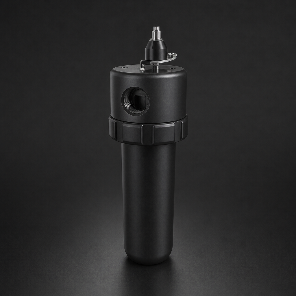
3. Zero-Loss (Float-Operated) Drains
Zero-loss drains use a float mechanism to open the drain valve only when condensate is actually present, and to close it before any compressed air escapes. They eliminate air loss entirely while ensuring the housing is drained continuously and automatically. This makes them the preferred solution for energy-conscious operations and for applications where consistent air quality is critical.
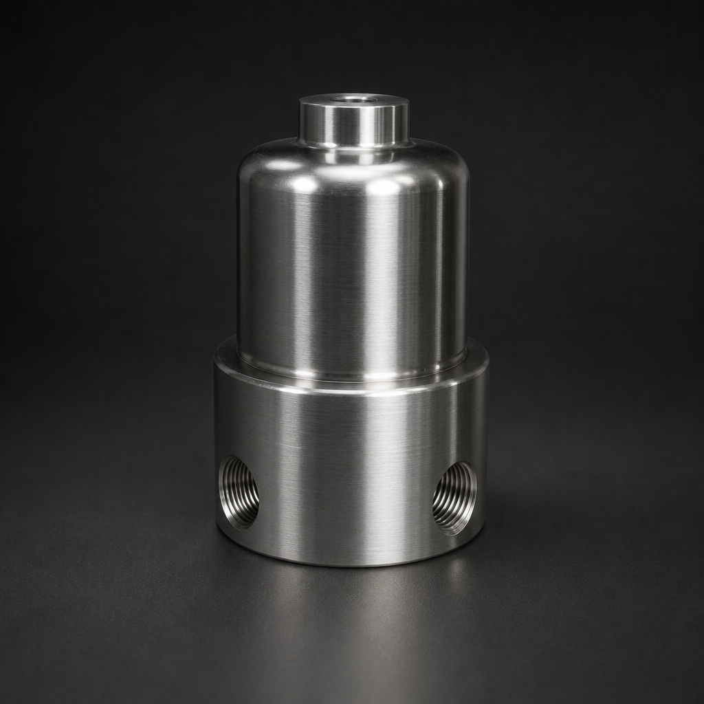
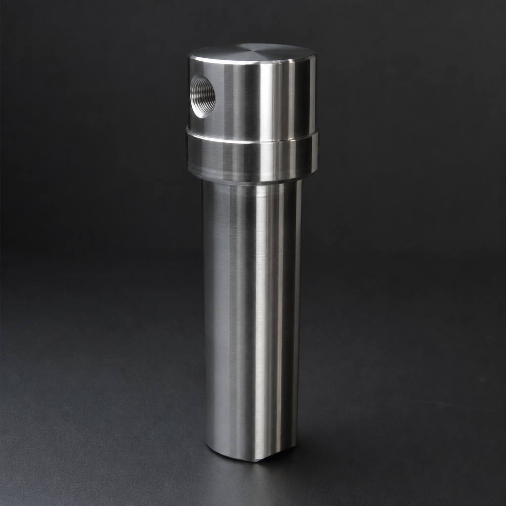
R+F FilterElements offers the RF-H compressed air filter range with an integrated float drain option, denoted by the F suffix in the model code (e.g., RF-H-385AI-F). The float mechanism is housed within the bowl assembly and requires no external power or control signal — it operates purely on the buoyancy of accumulated liquid.
Why Drain Performance Directly Affects Filter Performance
A coalescing filter element works by capturing sub-micron oil aerosols and water droplets on borosilicate glass microfibre, allowing them to coalesce into larger droplets that drain by gravity to the sump. The element can only drain effectively if the sump is kept clear. When a drain fails or is neglected, the sump fills, the liquid level rises into the element, and the element becomes flooded. At this point:
- Differential pressure across the element rises steeply — often triggering a bypass
- Re-entrainment occurs: high-velocity air picks up liquid from the flooded element and carries it downstream
- The element may be permanently damaged if liquid is forced through the microfibre structure under pressure
This is why R+F FilterElements recommends specifying the float-drain (F suffix) variant as standard for all coalescing filter stages. The RF-C coalescing elements fitted in the RF-H-310 to RF-H-395 series achieve 99.99 % efficiency at ≥ 0.1 µm — but only when the housing sump is properly drained.
Condensate collection and off-site disposal
R+F FilterElements RF-H Series: Drain Options and Specifications
The RF-H compressed air filter range covers flow rates from small point-of-use installations up to large centralised compressor rooms. The table below summarises key housing models and their drain configurations.
| Model | Max Flow (Nm³/h) | Max Pressure | Element Type | Float Drain Option | Typical Application |
|---|---|---|---|---|---|
| RF-H-310 | Up to 120 | 17 bar | RF-C / RF-P | RF-H-310-F | Small workshop, point-of-use |
| RF-H-340 | Up to 600 | 17 bar | RF-C / RF-P | RF-H-340-F | Medium compressor room |
| RF-H-360 | Up to 2,400 | 17 bar | RF-C / RF-P | RF-H-360-F | Industrial production line |
| RF-H-385AI | Up to 8,500 | 17 bar | RF-C / RF-P | RF-H-385AI-F | Large centralised system |
| RF-H-395 | Up to 12,000 | 17 bar | RF-C / RF-P | RF-H-395-F | High-flow compressor station |
All RF-H housings accept both RF-C coalescing elements (for oil aerosol and water mist removal) and RF-P particulate elements (for solid particle filtration). The float drain option is available across the full range and is specified simply by adding the F suffix to the model code when ordering.
Condensate Quality and Disposal
Compressed air condensate is not clean water. It contains emulsified compressor oil, rust particles, pipe scale, and potentially traces of process contaminants. In most European jurisdictions — including Germany, where R+F FilterElements is based — discharging oily condensate directly to drain is prohibited. Condensate must be treated before disposal.
The two principal treatment methods are:
- Oil-water separators — gravity or membrane-based units that separate the oil phase from the water phase, allowing compliant water discharge and oil collection for disposal
- Condensate collection and off-site disposal — suitable for smaller volumes where a separator is not cost-effective
When specifying your condensate management system, always account for the disposal route at the design stage. The drain outlet from your RF-H filter housing should be piped to a collection point or separator — never to an open drain.
Use our free Engineering Tool to get a filtration recommendation for your specific application in under 2 minutes.
Designing a Condensate Management Strategy
Effective condensate management requires a system-level approach, not just the selection of a single drain. Consider the following design principles:
Install Drains at Every Low Point
Condensate collects wherever air velocity drops and temperature falls. Every filter housing, receiver, aftercooler, and low point in the distribution ring main needs a drain. A single missed low point can become a reservoir that periodically discharges water slugs downstream.
Size Filters for Actual Flow — Not Nameplate Compressor Output
Oversized filters running at low velocity have poor coalescing efficiency; undersized filters flood quickly. Use the R+F sizing wizard to match housing size to actual system flow rate, operating pressure, and temperature. Correct sizing also ensures the float drain operates within its design flow range.
Stage Your Filtration
A typical compressed air filtration train consists of:
- A water separator or cyclonic pre-filter immediately after the aftercooler — to remove bulk liquid before it reaches the coalescing stage
- A coalescing filter (RF-C element) — to remove oil aerosols and fine water mist to ≤ 0.01 mg/m³
- A particulate filter (RF-P element) — to remove solid particles downstream of the coalescer
- An adsorption filter (RF-AC element) — where oil vapour removal to < 0.003 mg/m³ is required for critical applications
Each stage should have its own drain. The coalescing stage in particular generates the highest condensate volume and must never be allowed to flood. Explore the full R+F compressed air filter range to configure the right train for your system.
Monitor Differential Pressure
A rising differential pressure indicator on a coalescing filter is often the first sign of drain failure or element flooding. Fit differential pressure gauges or electronic transmitters to all coalescing stages and set an alarm at 0.5 bar above the clean element pressure drop. This gives operators time to investigate before the element is damaged or bypass occurs.
Maintain Drains Regularly
Float drains are reliable but not maintenance-free. Inspect and clean float mechanisms at least annually, or more frequently in systems with high condensate loads or contaminated air. Timer drains should have their intervals reviewed seasonally. Manual drains should be incorporated into a formal operator checklist.
Common Condensate Management Mistakes — and How to Avoid Them
| Mistake | Consequence | Correct Approach |
|---|---|---|
| Relying on manual drains without a maintenance schedule | Filter flooding, element damage, water carry-over | Specify float-drain (F suffix) RF-H housings as standard |
| Setting timer drain intervals too long in summer | Condensate accumulation between cycles | Adjust timer intervals seasonally; consider upgrading to zero-loss drains |
| No drain at the aftercooler outlet | Bulk liquid enters the filter train, overwhelming the coalescer | Install a water separator with float drain immediately after the aftercooler |
| Discharging condensate directly to drain | Environmental non-compliance, regulatory fines | Route condensate to an oil-water separator before discharge |
| Ignoring rising differential pressure | Element bypass, unfiltered air reaching process | Fit DP indicators and act on alarms promptly |
Specifying the Right Solution for Your System
Condensate management requirements vary significantly depending on compressor type, duty cycle, ambient conditions, and the sensitivity of the downstream process. A food-grade packaging line has very different requirements from a general workshop air supply. R+F FilterElements' engineering team can assist with system assessment, filter train design, and drain selection — contact us at the enquiry page or email [email protected].
For applications requiring compliance with ISO 8573-1 air quality classes, correct condensate management is a prerequisite — no filtration system can achieve Class 1 or Class 2 air quality if the drain is not functioning correctly. See our guide to ISO 8573-1 compressed air quality classes for a full breakdown of the standard and how to specify filters accordingly.
For a deeper understanding of how coalescing and particulate elements work together in a filtration train, read our technical comparison: Coalescing vs Particulate Filter Elements — Which Do You Need?
- Filter element flooding
- Drain selection is the single most important decision in condensate management.
- A coalescing filter element works by capturing sub-micron oil aerosols and water droplets on borosilicate glass microfibre, allowing them to coalesce into larger droplets that drain by gravity to the sump.
- The RF-H compressed air filter range covers flow rates from small point-of-use installations up to large centralised compressor rooms.
Summary
Condensate management is inseparable from filter performance. The best coalescing element in the world will fail if the housing sump is not kept clear. By specifying float-drain variants of the RF-H series — such as the RF-H-385AI-F or RF-H-360-F — and designing a complete condensate management strategy that covers every low point in the system, you protect your filter elements, your downstream equipment, and your process quality.
R+F FilterElements, a German-based filtration specialist, offers the full RF-H compressed air filter range with float-drain options across all housing sizes, paired with RF-C coalescing and RF-P particulate elements to meet ISO 8573-1 air quality requirements. Contact our team to discuss your specific condensate management challenge.