
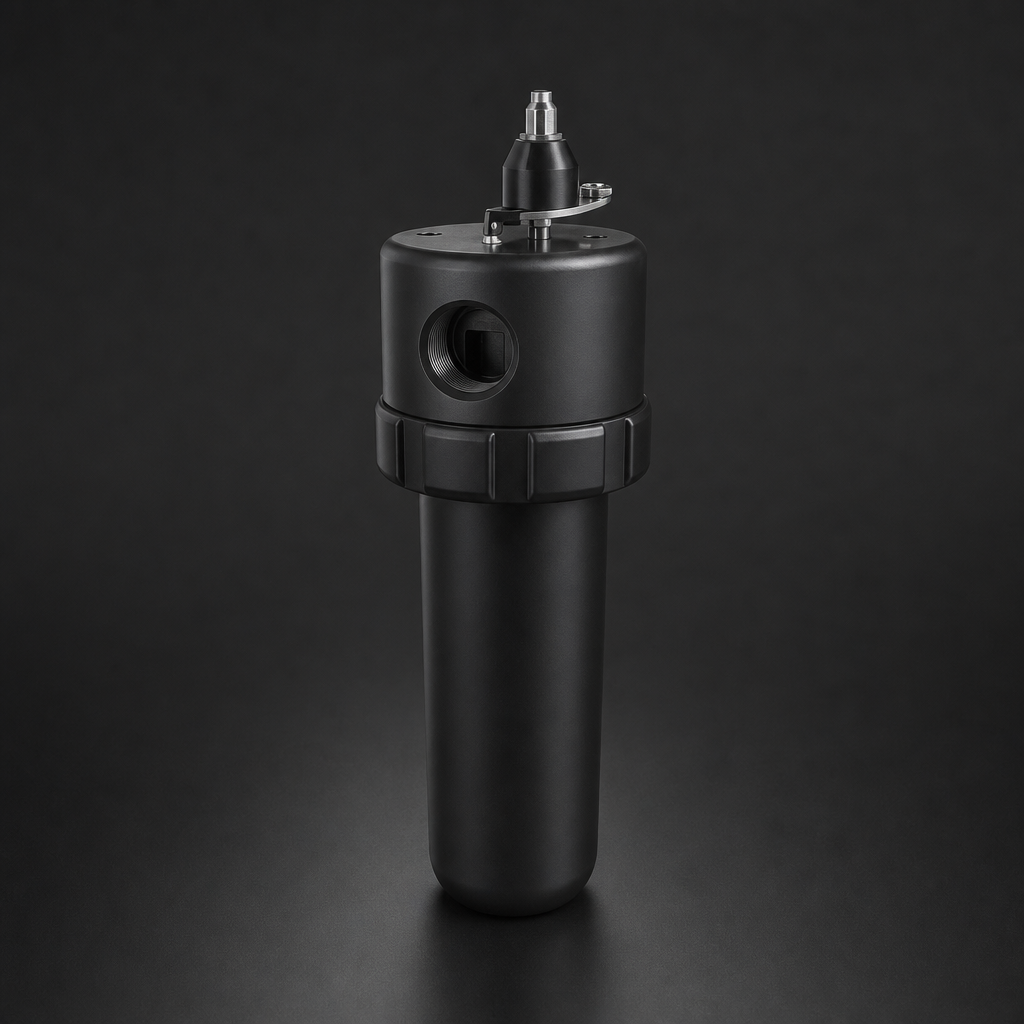
If your compressed air system's condensate drains are foaming, gurgling, or failing to open at the right moment, you are not dealing with a minor nuisance — you are looking at a system-wide contamination risk. Foaming condensate is one of the most common causes of auto drain failure, and when a drain fails, liquid backs up into filter housings, saturates filter elements, and allows oil-laden water to pass downstream unchecked.
This guide explains why foaming occurs, how it disrupts both timer-controlled and zero-loss drains, and what you can do to restore reliable drainage across your compressed air or process gas filtration system.
Why Condensate Foams in the First Place
Condensate in a compressed air system is never pure water. It is an emulsion of water, compressor lubricant, wear particles, and dissolved gases. When this mixture is agitated — by turbulent flow through pipework, pressure drops across valves, or rapid depressurisation at a drain orifice — it can foam vigorously.
The primary culprit is the oil-water emulsion. Compressor oils, particularly synthetic polyglycol and ester-based lubricants, are far more prone to emulsification than mineral oils. Once emulsified, the mixture has a dramatically lower surface tension, and any agitation produces a stable foam that does not collapse quickly. Surfactants from pipe-cleaning agents, rust inhibitors, or even certain seal materials can make the problem significantly worse.
Temperature also plays a role. Condensate collected at lower temperatures (below 15 °C) tends to be more stable as an emulsion. Warm condensate from a hot aftercooler outlet may separate more readily, but if it cools again in a receiver or distribution line before reaching the drain, emulsification can re-establish itself.
How Foaming Blocks Auto Drains
Auto drains — whether timer-controlled solenoid types or zero-loss float-operated designs — are engineered to discharge liquid, not foam. Foam presents two distinct failure modes depending on drain type.
Timer Drains
A timer drain opens for a fixed interval (typically 1–5 seconds) at a set frequency. When the condensate is foamy, the drain opens and discharges a mixture of foam and air rather than liquid. The actual volume of liquid expelled is a fraction of what the timer cycle was designed to remove. Over successive cycles, liquid accumulates in the filter housing sump faster than it is removed. Eventually the housing floods, the filter element becomes saturated, and liquid carryover begins downstream.
Timer drains also waste significant compressed air when set too aggressively. A drain that opens for 3 seconds every 15 minutes on a lightly loaded system can waste 5–10% of total compressed air production. Foaming makes this worse: operators often extend the open time to try to clear the foam, increasing air loss without solving the underlying problem.
Zero-Loss Drains
Zero-loss drains use a float mechanism to detect liquid level and open only when genuine liquid is present, discharging without air loss. Foam defeats this mechanism in a different way: the float rises on the foam column as if liquid were present, triggers the drain to open, and the drain discharges foam and air — not liquid. The float then drops, the drain closes, and the cycle repeats. In severe cases the drain chatters continuously, wearing the seat and valve, while the actual liquid level in the housing continues to rise.
The Consequences of Drain Failure
When condensate drainage fails, the consequences escalate quickly. The immediate effect is filter housing flooding: liquid rises above the element, bypasses filtration entirely, and carries oil and particulate contamination downstream. In a compressed air filtration system supplying pneumatic tools or instrumentation, this can cause valve seizure, actuator corrosion, and instrument damage.
In process gas applications — natural gas, biogas, or hydrogen — the stakes are higher still. Liquid carryover into analyser sample lines or process control instruments can cause measurement errors, instrument damage, or in the case of hydrogen, a safety-critical event. The ISO 8573-1 compressed air quality standard specifies maximum oil aerosol concentrations precisely because downstream contamination from failed filtration is a well-documented industrial hazard.
Need help selecting the right filter and drain configuration?
Drain Type Comparison: Timer vs Zero-Loss
| Feature | Timer Drain | Zero-Loss Drain |
|---|---|---|
| Operating principle | Fixed interval solenoid open/close | Float-actuated, level-triggered |
| Air loss | Significant (5–10% typical) | Zero (liquid only discharged) |
| Foam behaviour | Discharges foam instead of liquid; housing floods | Float rides foam; chatters; liquid accumulates |
| Maintenance requirement | Periodic solenoid and strainer cleaning | Float mechanism inspection; seat wear check |
| Best suited for | High condensate loads, low foam risk | Variable loads, energy-conscious installations |
Use our free Engineering Tool to get a filtration recommendation for your specific application in under 2 minutes.
Preventing and Resolving Foaming Condensate Drains
1. Address the Root Cause: Lubricant Compatibility
If foaming began after a lubricant change, consult your compressor manufacturer about switching to a mineral-based or low-emulsification synthetic. Some operators add a de-emulsifier to the compressor oil circuit, though this must be approved by the compressor OEM to avoid seal damage.
2. Install a Coalescing Pre-Filter Upstream of the Drain
A high-efficiency coalescing filter element — such as the RF-C series available from R+F FilterElements — captures oil aerosols before they can emulsify with condensate water. The RF-C element achieves 99.99% efficiency at ≥ 0.1 µm, removing the oil fraction that drives emulsification. Fitting an RF-C element in an RF-H-310 to RF-H-395 series housing upstream of your drain point significantly reduces the oil load reaching the drain sump.
For point-of-use protection or where space is limited, the RF-DIL disposable inline filter provides a compact coalescing stage that can be inserted directly into the condensate drain line.
3. Fit a Coalescing Drain Pot
A coalescing drain pot — a small vessel with a coalescing mesh insert — installed immediately upstream of the drain allows foam to collapse before it reaches the drain mechanism. The residence time in the pot (typically 10–30 seconds) is sufficient for most foams to break down into free liquid. This is a low-cost retrofit that can resolve foaming problems without changing the drain type.
4. Review Drain Sizing and Placement
Drains must be sized for the actual condensate load, which varies with ambient temperature, inlet humidity, and system pressure. A drain undersized for peak summer condensate production will struggle even without foaming. Ensure the drain is positioned at the lowest point of the filter housing sump, with no upward pipe runs between the housing outlet and the drain inlet that could trap foam.
5. Scheduled Drain Maintenance
Both timer and zero-loss drains require periodic maintenance. Strainers and orifices should be cleaned every 3–6 months in systems with high oil carryover. Float mechanisms should be inspected annually for wear, corrosion, or foam-induced seat damage. Keeping a maintenance log tied to filter element change intervals ensures drain servicing is not overlooked.
Selecting the Right Filter Housing for Reliable Drainage
Filter housing design directly affects drainage reliability. Housings with large sump volumes provide more residence time for foam to collapse before reaching the drain. The R+F FilterElements RF-H series compressed air housings are designed with generous sump geometry and a bottom-ported drain connection that minimises turbulence at the drain inlet.
For process gas applications where condensate foaming is a known risk — particularly in biogas and landfill gas systems where surfactant-rich condensate is common — the RF-H-150 process gas housing (rated to 100 bar, 316L stainless steel) provides a robust platform with a bottom drain port suitable for both timer and zero-loss drain configurations. Pair it with an RF-C coalescing element to maximise oil removal upstream of the drain point.
Where activated carbon adsorption is required to remove oil vapour downstream of the coalescing stage, the RF-AC adsorption element reduces residual oil content to below 0.003 mg/m³, meeting the most demanding ISO 8573-1 Class 1 oil vapour requirements.
- Condensate in a compressed air system is never pure water.
- Auto drains — whether timer-controlled solenoid types or zero-loss float-operated designs — are engineered to discharge liquid, not foam.
- When condensate drainage fails, the consequences escalate quickly.
- If foaming began after a lubricant change, consult your compressor manufacturer about switching to a mineral-based or low-emulsification synthetic.
Related Reading
- Coalescing vs Particulate Filter Elements — Which Do You Need?
- ISO 8573-1 Compressed Air Quality — A Practical Guide
- Crankcase Ventilation Filtration — Protecting Your Compressor
Try our Engineering Sizing Tool → or discuss your requirements with our team.

