When specifying a coalescer element for compressed air or process gas duty, engineers face a fundamental design choice: depth-loading borosilicate microfibre or pleated glass fibre. Both remove liquid aerosols, but they do so through different mechanisms — and the differences in performance, service life, and pressure drop are significant. This guide explains how each design works and why depth-loading microfibre consistently outperforms pleated alternatives in demanding applications.
How Coalescence Actually Works
Liquid aerosols in compressed air exist as fine droplets, typically 0.01–5 µm in diameter. A coalescer element must capture these droplets, allow them to merge into larger drops, and drain them away before they re-entrain into the gas stream. The efficiency of this process depends almost entirely on the filter medium's structure and depth.
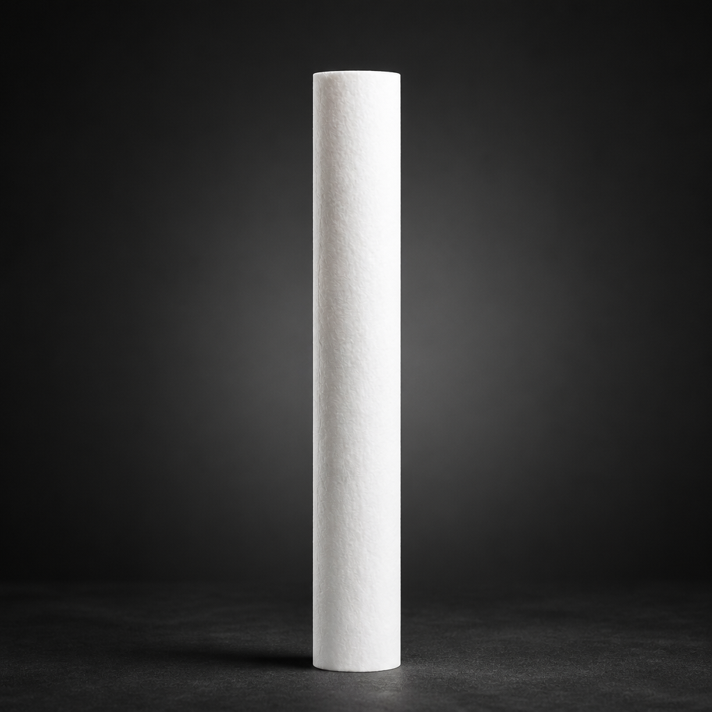
Depth-loading elements, such as the RF-C coalescing element range, use a thick bed of randomly oriented borosilicate glass microfibres. As the aerosol-laden gas passes through this bed, droplets are captured progressively at multiple fibre layers. Captured droplets migrate along fibres under surface tension forces, merge with neighbouring droplets, and eventually drain by gravity to the element's outer surface, where they fall into the housing sump.
Pleated designs — such as the 7CVP-type elements used in some OEM housings — fold a thinner sheet of glass fibre into a pleated geometry to increase surface area. This increases the available filtration area per unit volume, which can reduce initial pressure drop. However, the reduced media depth fundamentally limits the coalescence mechanism.
Depth-Loading: The Mechanism Advantage
The physics of coalescence favour depth. A thicker fibre bed provides:
- Multiple capture opportunities — a droplet that passes the first fibre layer encounters dozens more before exiting
- Longer residence time — slower interstitial velocity allows diffusion to act on sub-micron droplets
- Larger coalescence zones — droplets have more fibre surface area over which to migrate and merge
- Better drainage separation — the thick bed acts as a physical barrier between the inlet gas and the draining liquid
Dirt-Holding Capacity and Service Life
In real compressed air systems, the coalescer must handle not only liquid aerosols but also solid particulate contamination — rust, pipe scale, compressor wear debris, and atmospheric dust that bypasses the inlet filter. This is where depth-loading elements hold a decisive advantage.
A thick fibre bed distributes particulate loading across its entire depth. Solid particles are captured at different layers depending on their size, and the element can accumulate a substantial mass of contamination before pressure drop rises to the change-out threshold. Pleated elements, by contrast, load primarily on their upstream surface. Once the surface is blinded, pressure drop rises steeply and the element must be replaced — often well before its theoretical liquid-removal capacity is exhausted.
Need help selecting the right coalescer element?
Pressure Drop: Initial vs. Lifetime
Pleated elements often show a lower initial pressure drop than depth-loading designs, because the increased surface area reduces face velocity. This can appear attractive on a datasheet. However, the relevant metric for operating cost is not initial pressure drop but average pressure drop over the service interval.
Because pleated elements blind more rapidly, their pressure drop rises faster. A depth-loading element may start slightly higher but remain relatively stable for a much longer service period. Over a 12-month operating cycle, the integrated energy cost of a pleated element frequently exceeds that of a depth-loading alternative — even before accounting for the additional replacement labour and element cost.
For a detailed look at how filter selection affects compressed air quality standards, see our guide to ISO 8573-1 compressed air quality classes.
Use our free Engineering Tool to get a filtration recommendation for your specific application in under 2 minutes.
Head-to-Head Comparison
| Parameter | Depth-Loading Microfibre (RF-C) | Pleated Glass Fibre (7CVP-type) |
|---|---|---|
| Coalescence mechanism | Multi-layer depth capture + drainage | Surface capture + limited drainage |
| Efficiency ≥ 0.1 µm | 99.99% (ISO 12500-1) | Typically 99.9% or lower |
| Initial pressure drop | Moderate (0.2–0.5 bar) | Low (0.1–0.3 bar) |
| Dirt-holding capacity | High — distributed through depth | Low — surface blinding |
| Typical service interval | 8,000–12,000 h | 2,000–6,000 h |
| Re-entrainment risk | Low — thick bed prevents blowback | Higher at elevated flow rates |
| ISO 8573-1 Class achievable | Class 1 oil aerosol | Class 2–3 typically |
ISO 12500-1 Testing and What It Reveals
ISO 12500-1 is the international standard for testing coalescing filter elements under defined conditions of flow, inlet concentration, and temperature. It specifies a challenge aerosol of Dioctyl Sebacate (DEHS) at a defined concentration and measures the downstream residual. The test is deliberately challenging — it uses a fine, stable aerosol that is harder to coalesce than the heavier oil mists found in most industrial systems.
R+F branded RF-C coalescing elements are rated to 99.99% efficiency at ≥ 0.1 µm under ISO 12500-1 conditions. This corresponds to a residual oil aerosol concentration of < 0.01 mg/m³ at rated flow — meeting ISO 8573-1 Class 1 for oil aerosol. Pleated designs tested under the same standard typically achieve 99.9% or lower, placing them in Class 2 or Class 3 — a meaningful difference for food-grade, pharmaceutical, or instrument air applications.
For applications where both liquid aerosol and vapour-phase oil must be removed, an RF-C coalescer should be followed by an RF-AC activated carbon adsorber, which reduces residual oil vapour to < 0.003 mg/m³. See our article on coalescing vs. particulate filter elements for guidance on sequencing filter stages correctly.
Selecting the Right Housing
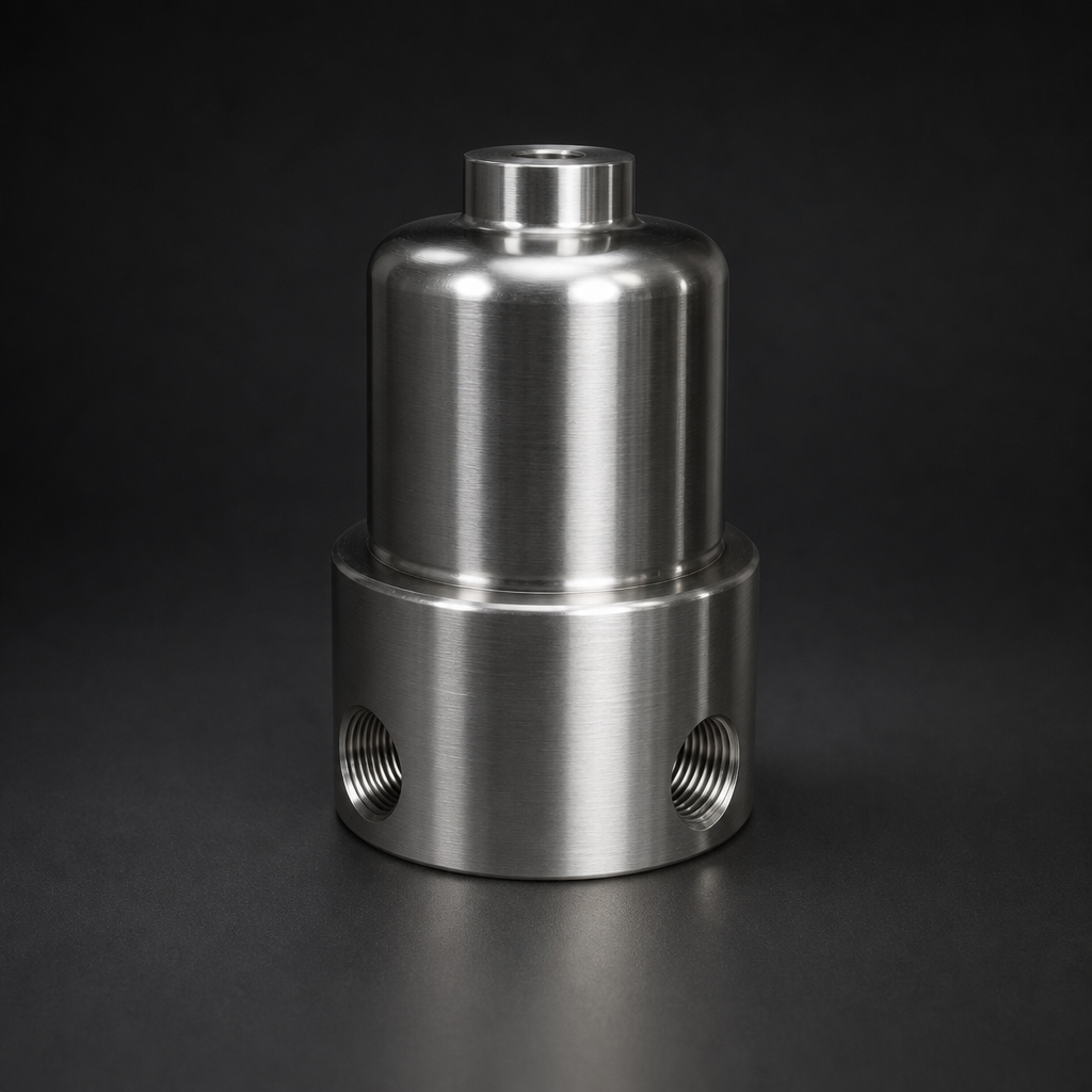
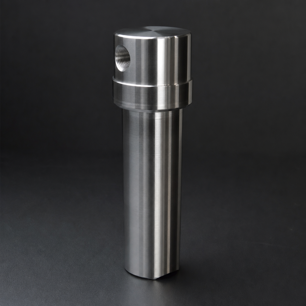
RF-C elements are available in six standard sizes (12032, 12057, 25064, 25178, 51230, 51476) and fit the RF-H-310 to RF-H-395 compressed air filter housing range. These aluminium housings are rated to 17 bar and handle flows from a few Nm³/h up to 12,000 Nm³/h in multi-element configurations. For process gas or higher-pressure duties, the same element technology is available in 316L stainless steel housings — contact our team for sizing assistance.
When replacing 7CVP-type or other OEM pleated elements, R+F FilterElements can supply direct-fit RF-C replacements for most common housing sizes. Our Engineering Sizing Tool allows you to enter your flow rate, operating pressure, and housing model to identify the correct RF-C element and verify pressure drop at your operating conditions.
- Liquid aerosols in compressed air exist as fine droplets, typically 0.
- Multiple capture opportunities
- In real compressed air systems, the coalescer must handle not only liquid aerosols but also solid particulate contamination — rust, pipe scale, compressor wear debris, and atmospheric dust that bypasses the inlet filter.
- Pleated elements often show a lower initial pressure drop than depth-loading designs, because the increased surface area reduces face velocity.
Related Reading
- Coalescing vs. Particulate Filter Elements — When to Use Each
- ISO 8573-1 Compressed Air Quality Classes Explained
- Crankcase Ventilation Filtration — Protecting Your Compressor
Try our Engineering Sizing Tool → or discuss your requirements with our team.