
Why 'Oil-Free' Does Not Mean 'Contaminant-Free'
The term oil-free compressor is one of the most misunderstood phrases in industrial compressed air. Procurement teams specify oil-free machines, quality managers sign off on the installation, and production lines run — all under the assumption that the air is clean. In many cases, it is not.
An oil-free compressor is designed so that no lubricating oil enters the compression chamber. That is a genuine engineering achievement, and it eliminates one significant contamination route. But it does not address what happens to the air before it enters the compressor, what forms during compression, or what the machine itself contributes through normal mechanical wear. Understanding these three contamination pathways is the first step towards a filtration strategy that actually protects your process.
Contaminant 1: Atmospheric Oil Vapour
Every compressor — oil-free or otherwise — draws in ambient air. That air is never truly clean. In a typical industrial or urban environment, atmospheric air contains between 0.05 and 0.5 mg/m³ of oil vapour, originating from vehicle exhausts, nearby machinery, cleaning solvents, and general industrial activity. A compressor running at 10,000 Nm³/h can therefore introduce up to 5 kg of oil vapour into your system every day, even if the machine itself contributes zero oil.
This matters because compression concentrates contaminants. As air is compressed from atmospheric pressure to, say, 7 bar(g), the volume reduces by roughly a factor of eight. The oil vapour concentration in the compressed air rises proportionally. What was a marginal 0.1 mg/m³ at the inlet can become 0.8 mg/m³ or more at the outlet — well above the limits required for food-grade, pharmaceutical, or electronics manufacturing applications.
ISO 8573-1 Class 0, the most stringent classification for total oil content, requires a concentration of less than 0.01 mg/m³. Achieving that from an inlet concentration of 0.1 mg/m³ or higher demands active filtration — specifically, a combination of coalescing and adsorption stages. An oil-free compressor alone cannot get you there.
Contaminant 2: Condensate
Compression raises the temperature of air significantly. As that air cools — in the aftercooler, in distribution pipework, or at the point of use — water vapour condenses into liquid droplets. This is not a fault condition; it is basic thermodynamics. Even in a dry climate, a compressor handling 1,000 Nm³/h of air at 20 °C and 60% relative humidity will produce approximately 25–30 litres of condensate per hour at 7 bar(g).
Condensate is not simply water. It carries dissolved carbon dioxide (forming carbonic acid), atmospheric particulates, and — critically — any oil vapour that has condensed alongside it. The resulting liquid is mildly acidic and can contain emulsified oil at concentrations that cause corrosion, microbial growth, and product contamination if it reaches downstream equipment or processes.
A coalescing filter positioned after the aftercooler and refrigerant dryer is the standard defence. It captures bulk liquid droplets and sub-micron aerosols before they travel further into the system. Without it, even a perfectly functioning refrigerant dryer will pass liquid slugs during transient conditions such as start-up, load changes, or ambient temperature spikes.
Contaminant 3: Wear Particles
Oil-free compressors rely on alternative materials to manage friction in the absence of lubricating oil. Common approaches include PTFE-coated pistons, carbon-graphite rings, and ceramic-coated rotors. These materials are durable, but they are not indestructible. Over time — and particularly as components age — they shed sub-micron particles into the compressed air stream.
Carbon particles from graphite rings are a well-documented example. They are typically in the 0.1–1 µm size range, which means they pass straight through coarse particulate filters and can travel deep into pneumatic instruments, control valves, and process analysers. In semiconductor fabrication or sterile pharmaceutical filling, even trace carbon contamination can trigger a batch rejection or instrument failure.
PTFE wear debris presents a similar challenge. Although chemically inert, PTFE particles at sub-micron sizes can foul sensitive flow meters, block analyser sample lines, and accumulate on valve seats. The solution is a high-efficiency particulate filter — rated to remove particles down to 0.01 µm — positioned as close to the point of use as practical.
time-based replacement interval of 4,000 operating hours
The Correct Filtration Strategy for Oil-Free Compressor Systems
Addressing all three contamination sources requires a staged approach. A single filter type cannot handle liquid aerosols, oil vapour, and sub-micron solid particles simultaneously with optimal efficiency. The recommended sequence for a compressed air system serving critical applications is as follows:
| Stage | Filter Type | Target Contaminant | Typical ISO 8573-1 Contribution |
|---|---|---|---|
| 1 — Pre-filter | Coalescing (general purpose) | Bulk liquid, large aerosols ≥ 1 µm | Oil aerosol Class 2 (≤ 0.1 mg/m³) |
| 2 — High-efficiency coalescing | Coalescing (high efficiency) | Sub-micron aerosols ≥ 0.01 µm | Oil aerosol Class 1 (≤ 0.01 mg/m³) |
| 3 — Adsorption | Activated carbon | Oil vapour (gaseous phase) | Total oil Class 0 (≤ 0.003 mg/m³) |
| 4 — Final particulate | Particulate (0.01 µm) | Carbon/PTFE wear particles | Particle Class 1 (≤ 0.1 mg/m³) |
This four-stage arrangement is not always necessary for every application. A food-grade packaging line will typically require all four stages, whereas a general workshop air supply may need only stages 1 and 2. The key is to assess the actual contamination risk at each point of use rather than assuming the compressor type determines the air quality.
R+F FilterElements Solution: RF-H-360AI and Matched Elements
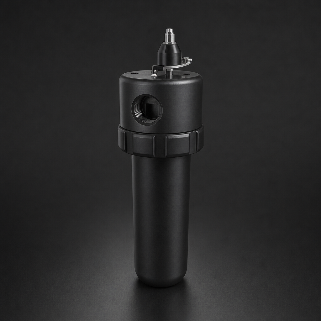
For compressed air systems in the flow range up to 3,600 Nm³/h, R+F FilterElements offers the RF-H-360AI aluminium filter housing as the primary solution for oil-free compressor applications. The housing accepts both RF-C coalescing elements and RF-P particulate elements in the same body, simplifying installation and reducing the number of connection points in the pipework.
The RF-C coalescing elements used in the RF-H-360AI are manufactured from borosilicate glass microfibre with a graded-density structure. They achieve 99.99% efficiency for aerosols ≥ 0.01 µm and are rated for continuous operation at up to 100 °C (S-type elements extend this to 200 °C for high-temperature aftercooler bypass applications). Residual oil aerosol content downstream is ≤ 0.01 mg/m³, meeting ISO 8573-1 Class 1.
Where total oil content must reach Class 0, an RF-AC adsorption element is installed in a downstream housing. The activated carbon bed reduces residual oil vapour to less than 0.003 mg/m³ — well within Class 0 requirements — and has a service life of approximately 4,000 operating hours under normal conditions.
For the final particulate stage, RF-P elements in the RF-H-360AI provide 99.99% efficiency for particles ≥ 0.3 µm, capturing carbon and PTFE wear debris before it reaches sensitive downstream equipment. All elements are available in standard sizes 12032, 12057, 25064, 25178, 51230, and 51476 to match the housing configuration to the required flow rate.
Use our free Engineering Tool to get a filtration recommendation for your specific application in under 2 minutes.
Sizing and Pressure Drop Considerations
One practical concern with multi-stage filtration is cumulative pressure drop. Each filter stage adds resistance to flow, and in a compressed air system operating at 7 bar(g), even a modest 0.1 bar pressure drop per stage represents a measurable energy cost. Over a year of continuous operation, four stages at 0.1 bar each can add up to a significant increase in compressor energy consumption.
The solution is correct sizing. A filter housing operating at 50–70% of its rated maximum flow will typically show a pressure drop of 0.02–0.05 bar across a clean element — well below the 0.1 bar threshold that triggers element replacement. Oversizing by one housing size is often the most cost-effective decision over the life of the installation.
R+F FilterElements provides a free online sizing tool that calculates the correct housing size and element configuration based on your flow rate, operating pressure, and temperature. It also estimates annual energy costs associated with pressure drop, making it straightforward to justify the capital cost of correct sizing to procurement teams.
Maintenance: What Changes with Oil-Free Systems
A common misconception is that oil-free compressor systems require less frequent filter maintenance because there is no bulk oil to saturate the elements. In practice, the opposite is often true. Because the oil loading on coalescing elements is lower, the elements may appear clean for longer — but the particulate loading from atmospheric dust and wear debris continues to accumulate. Relying on visual inspection or differential pressure alone can lead to elements being left in service beyond their effective life.
R+F recommends a time-based replacement interval of 4,000 operating hours for RF-C and RF-P elements in oil-free compressor applications, regardless of differential pressure readings. For RF-AC adsorption elements, the interval is the same, but breakthrough monitoring (using an oil vapour detector downstream) is advisable in Class 0 applications where any lapse in performance is unacceptable.
All RF-H-360AI housings are fitted with differential pressure indicators as standard, providing a secondary check. If the indicator triggers before the 4,000-hour interval, it is a signal to investigate the upstream system — a sudden increase in particulate loading often indicates a worn compressor component that requires attention.
Compliance and Documentation
For regulated industries — food and beverage, pharmaceuticals, medical devices — documenting compressed air quality is not optional. ISO 8573-1 provides the classification framework, but auditors increasingly require evidence that the filtration system is correctly specified, properly maintained, and capable of delivering the claimed air quality class.
R+F FilterElements supplies full technical documentation for all RF-H and RF-C/RF-P/RF-AC products, including efficiency test certificates, material declarations, and installation drawings. This documentation package supports validation activities under FDA 21 CFR Part 11, EU GMP Annex 1, and EHEDG guidelines. For applications requiring traceability to specific batch numbers, elements are individually serialised on request.
For a detailed overview of how coalescing and particulate elements differ in construction and application, see our guide to coalescing vs particulate filter elements. For the full ISO 8573-1 classification system and how to specify air quality for your application, refer to our ISO 8573-1 compressed air quality guide.
To explore the full range of compressed air filter housings and elements available from R+F FilterElements, visit the compressed air filtration product range or use the engineering sizing tool to configure a solution for your specific operating conditions.
- Every compressor — oil-free or otherwise — draws in ambient air.
- Compression raises the temperature of air significantly.
- Oil-free compressors rely on alternative materials to manage friction in the absence of lubricating oil.
- Addressing all three contamination sources requires a staged approach.
Summary
Oil-free compressors are a sound choice for applications where lubricant contamination must be minimised at source. But they do not eliminate the need for downstream filtration. Atmospheric oil vapour, condensate, and internal wear particles are all present in the compressed air from an oil-free machine, and all three require active filtration to meet the quality levels demanded by modern industrial processes.
A correctly specified four-stage filtration train — coalescing, high-efficiency coalescing, adsorption, and final particulate — using R+F FilterElements RF-H-360AI housings with matched RF-C, RF-AC, and RF-P elements will reliably achieve ISO 8573-1 Class 0 total oil content and Class 1 particulate quality. Correct sizing, time-based maintenance intervals, and proper documentation complete the picture.
If you are reviewing the filtration specification for an existing oil-free compressor installation, or specifying a new system, R+F FilterElements is available to provide technical support. Contact the team at process-gas-filter.com/contact or email [email protected] for application-specific guidance.

