
Gas and steam turbines rely on pressurised lube oil systems to keep their bearing housings lubricated and cool. As oil circulates at high velocity through these housings, it atomises into a fine aerosol — commonly called oil mist — that must be vented to prevent pressure build-up. Left unmanaged, that mist escapes into the turbine hall, coats surfaces, and — critically — contacts hot exhaust casings or steam pipes where it becomes a serious fire and explosion hazard.
For plant engineers responsible for turbine reliability and site safety, selecting the correct coalescing vent filter for bearing housing vents is not a minor detail. It is a safety-critical decision that also affects oil consumption, housekeeping costs, and environmental compliance.
Why Turbine Bearing Housings Generate Oil Mist
Journal bearings in gas and steam turbines are fed with ISO VG 32–68 mineral or synthetic lube oil at supply pressures of 1–3 bar. As the shaft rotates at 3,000–3,600 rpm (or higher for aeroderivative machines), the oil film shears and a proportion is flung off as fine droplets. These droplets, combined with air drawn in through labyrinth seals, create a pressurised oil-mist atmosphere inside the bearing housing.
The vent path — typically a 1″ to 2″ BSP or flanged connection on the top of the housing — must relieve this pressure continuously. Without filtration, the escaping mist:
- Deposits oil on walkways, creating slip hazards
- Contaminates insulation on adjacent steam pipework
- Presents an ignition risk near hot surfaces (>250 °C)
- Triggers environmental permit breaches for oil-in-air emissions
Key Performance Requirements for a Turbine Lube Oil Vent Filter
Coalescing Filter Technology for Oil Mist Capture
Coalescing filters work by passing the oil-mist-laden air through a depth-loading borosilicate glass microfibre matrix. Submicron droplets are captured by interception, impaction, and diffusion mechanisms. As droplets accumulate within the fibre bed, they coalesce into larger droplets that drain by gravity into a sump at the base of the housing, from where they are returned to the lube oil reservoir via a drain line.
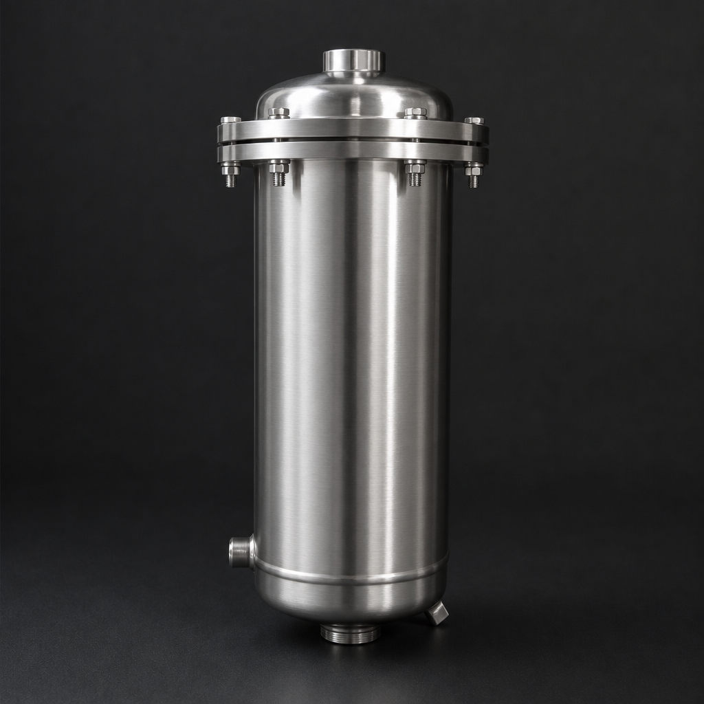
This drain-back feature is essential for turbine vent applications: the recovered oil reduces top-up frequency and prevents the environmental liability of oil-contaminated condensate. R+F FilterElements offers the RF-H-447S stainless steel vacuum-style housing specifically sized for turbine bearing vent duties, paired with RF-CS silica-bonded coalescing elements rated to 200 °C.
For smaller turbines or auxiliary bearing housings, the compact RF-H-420 aluminium housing with a single RF-C-25064 coalescing element provides an economical solution where temperatures remain below 120 °C. Both housings feature a bottom drain port and a differential pressure indicator to signal element replacement.
Learn more about the full vacuum pump exhaust filter range and how the same coalescing principles apply to vacuum pump oil mist elimination.
Need help selecting the right turbine bearing vent filter?
Comparing Vent Filter Designs: What to Specify
| Parameter | RF-H-420 (Aluminium) | RF-H-447S (316L SS) |
|---|---|---|
| Max operating temperature | 120 °C | 200 °C (with RF-CS element) |
| Housing material | Anodised aluminium | 316L stainless steel |
| Flow range (free air) | 5–120 m³/h | 20–765 m³/h |
| Element type | RF-C coalescing (standard) | RF-CS coalescing (silica-bonded) |
| Drain connection | ¼″ BSP bottom drain | ½″ BSP bottom drain |
| Typical application | Auxiliary / small turbines | Main gas / steam turbines |
Use our free Engineering Tool to get a filtration recommendation for your specific application in under 2 minutes.
Installation and Sizing Considerations
Correct sizing of a turbine bearing vent filter requires knowing the bearing housing vent flow rate — typically expressed as free air delivery (FAD) in m³/h. This is not always documented in the OEM manual, but can be estimated from the number of bearings, shaft speed, and labyrinth seal leakage rates. As a rule of thumb, a single journal bearing on a 50 MW gas turbine vents approximately 5–15 m³/h of oil-mist-laden air.
The filter should be mounted vertically with the drain at the bottom to allow gravity drainage of coalesced oil. A drain line of at least 300 mm height above the oil reservoir is recommended to create a positive head for drain-back without a pump. Where drain-back is not feasible, a float-operated drain valve or manual drain schedule must be implemented.
For guidance on sizing your specific installation, use the R+F Engineering Sizing Tool, which calculates the correct housing and element combination based on your flow, temperature, and pressure parameters.
The design principles for turbine bearing vent filters closely mirror those used in vacuum pump exhaust filtration — both applications involve oil-mist-laden gas at near-atmospheric pressure requiring coalescing separation before discharge. Engineers familiar with vacuum exhaust filter selection will find the transition to turbine vent filter specification straightforward.
Element Selection: Standard vs. High-Temperature
The choice between standard RF-C coalescing elements and the high-temperature RF-CS silica-bonded variant depends on the gas temperature at the vent connection. On steam turbines, bearing housing vent temperatures can reach 80–150 °C due to proximity to hot steam casings. On gas turbines, temperatures at the vent are typically lower (40–80 °C) but can spike during load transients.
The RF-CS element uses a silica binder system instead of the standard resin binder, allowing continuous operation to 200 °C without binder degradation or element collapse. This is the same element technology used in the RF-H-420 to RF-H-456 vacuum exhaust filter series. For applications where temperatures are confirmed below 100 °C, the standard RF-C element in sizes 25064 or 51230 provides excellent performance at lower cost.
All R+F branded coalescing elements achieve 99.99% efficiency for aerosol droplets ≥ 0.1 µm, meeting the requirements of ISO 8573-1 Class 1 oil aerosol when used in the correct housing. See our guide to coalescing vs. particulate filter elements for a full comparison of element technologies.
Maintenance and Change-Out Intervals
Unlike compressed air filters where differential pressure rise is the primary change-out trigger, turbine bearing vent filters often operate at very low differential pressures throughout their service life. The dominant failure mode is not pressure drop but rather element saturation with degraded oil, varnish deposits, or particulate contamination from worn bearing surfaces.
R+F FilterElements recommends annual element replacement aligned with planned turbine outages, regardless of differential pressure readings. Where continuous monitoring is required, a 4–20 mA differential pressure transmitter can be fitted to the housing to integrate with the plant DCS. Contact our team via the enquiry page to discuss monitoring options for your installation.
- Journal bearings in gas and steam turbines are fed with ISO VG 32–68 mineral or synthetic lube oil at supply pressures of 1–3 bar.
- Coalescing filters work by passing the oil-mist-laden air through a depth-loading borosilicate glass microfibre matrix.
- Correct sizing of a turbine bearing vent filter requires knowing the bearing housing vent flow rate — typically expressed as free air delivery (FAD) in m³/h.
- The choice between standard RF-C coalescing elements and the high-temperature RF-CS silica-bonded variant depends on the gas temperature at the vent connection.
Related Reading
- Crankcase Ventilation Filtration — Principles and Product Selection
- Coalescing vs. Particulate Filter Elements: Which Do You Need?
- ISO 8573-1 Compressed Air Quality Classes Explained
Try our Engineering Sizing Tool → or discuss your requirements with our team.

