Breathing air is not simply compressed air. When workers rely on supplied air for respiratory protection — whether operating SCBA sets, supplied-air respirators, or fixed breathing air panels — the quality of that air is a matter of life and safety. Two standards govern what "safe" means: EN 12021 in Europe and OSHA 29 CFR 1910.134 / CGA Grade D in the United States. Meeting either standard demands a carefully staged filtration train, and understanding each stage is the first step to protecting your workforce.
Why Compressed Air Is Not Breathing Air
A standard industrial compressor delivers air that is contaminated with oil aerosols, water vapour, particulates, carbon monoxide from combustion, and hydrocarbon vapours from lubricants. ISO 8573-1 Class 1 compressed air — the cleanest general-purpose grade — still permits up to 0.01 mg/m³ of oil and does not address CO or CO₂ at all. Breathing air standards are far stricter, and they add contaminants that industrial standards ignore entirely.
The practical consequence is that a breathing air system must treat the compressor output through multiple dedicated stages before it reaches a worker's lungs. Skipping or undersizing any stage creates a compliance gap — and a potential fatality.
The Four Mandatory Filtration Stages
A compliant breathing air system requires four sequential treatment stages. Each addresses a distinct class of contaminant, and each must be sized correctly for the system flow rate and operating pressure.
Stage 1 — Particulate Pre-Filter
Bulk particulates — rust, pipe scale, compressor wear debris — must be removed before they reach the finer downstream stages. A coarse particulate filter (typically rated at 1–5 µm) protects the coalescer from premature loading and extends the service life of the entire train. For breathing air systems, R+F RF-P particulate elements in the appropriate housing provide 99.99% efficiency at ≥ 0.3 µm, capturing all bulk contamination before it can reach the coalescer.
Stage 2 — Coalescing Filter
Oil aerosols and water droplets are the primary challenge for any compressor-fed system. A high-efficiency coalescer using borosilicate glass microfibre media — such as the R+F RF-C coalescing element — achieves 99.99% efficiency at ≥ 0.1 µm, reducing oil aerosol to well below 0.01 mg/m³. This single stage brings the air within reach of EN 12021 and CGA Grade D oil limits, provided the downstream adsorber handles residual vapour.
Stage 3 — Activated Carbon Adsorber
Oil vapour, hydrocarbon odours, and taste contaminants require adsorption, not filtration. An activated carbon stage — using R+F RF-AC adsorption elements — reduces residual oil vapour to below 0.003 mg/m³ and eliminates odour and taste. This stage is mandatory for EN 12021 compliance and is strongly recommended for CGA Grade D systems where odour-free air is required. Carbon beds have a finite capacity and must be changed on a scheduled basis — typically every 3–6 months depending on inlet oil concentration and flow rate.
Stage 4 — CO/CO₂ Catalytic Converter or Monitoring
Carbon monoxide is the most dangerous contaminant in breathing air and the hardest to remove by filtration alone. EN 12021 limits CO to 15 ppm; OSHA 29 CFR 1910.134 limits it to 10 ppm for Grade D air. Where the compressor intake is near combustion sources (vehicle exhausts, generators, welding areas), CO breakthrough is a real risk. Options include catalytic CO converters (which oxidise CO to CO₂ at elevated temperature) and continuous CO monitoring with automatic shut-off. Many high-integrity systems use both.
EN 12021 vs CGA Grade D — Key Differences
| Parameter | EN 12021 (Europe) | CGA Grade D / OSHA (US) |
|---|---|---|
| Oxygen content | 21 ± 1% v/v | 19.5–23.5% v/v |
| Carbon monoxide (CO) | ≤ 15 ppm | ≤ 10 ppm |
| Carbon dioxide (CO₂) | ≤ 500 ppm | ≤ 1,000 ppm |
| Oil (aerosol + vapour) | ≤ 0.5 mg/m³ | ≤ 5 mg/m³ |
| Water vapour (dew point) | ≤ −11 °C at line pressure | Not specified (odour-free) |
| Odour / taste | None perceptible | None perceptible |
The tighter EN 12021 oil limit (0.5 mg/m³ vs 5 mg/m³) means European systems must achieve a higher coalescing and adsorption performance. A two-stage approach — RF-C coalescer followed by RF-AC adsorber — comfortably meets both standards when correctly sized.
CO monitor / catalytic converter:
Breathing Air System Performance at a Glance
Use our free Engineering Tool to get a filtration recommendation for your specific application in under 2 minutes.
Filter Change Schedules and Monitoring
Breathing air systems are only as safe as their maintenance regime. Unlike industrial compressed air filters — where a differential pressure gauge is the primary change indicator — breathing air filters must be changed on a time-based schedule regardless of differential pressure, because activated carbon beds can become saturated with oil vapour without showing any pressure drop increase.
Recommended change intervals for a typical breathing air system operating at 7–10 bar:
- RF-P particulate pre-filter: every 6–12 months, or when differential pressure exceeds 0.5 bar
- RF-C coalescing element: every 6 months, or when differential pressure exceeds 0.5 bar
- RF-AC activated carbon adsorber: every 3–6 months — time-based, not pressure-based
- CO monitor / catalytic converter: per manufacturer's service schedule, typically annually
For SCBA filling stations and high-duty breathing air panels, quarterly air quality testing by an accredited laboratory is strongly recommended. This provides documentary evidence of compliance with EN 12021 or CGA Grade D and identifies any upstream contamination before it reaches workers.
Selecting the Right Housing for Your Breathing Air System
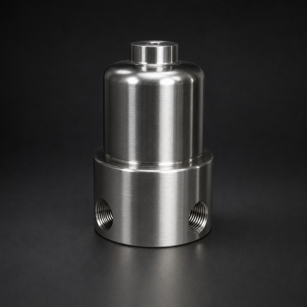
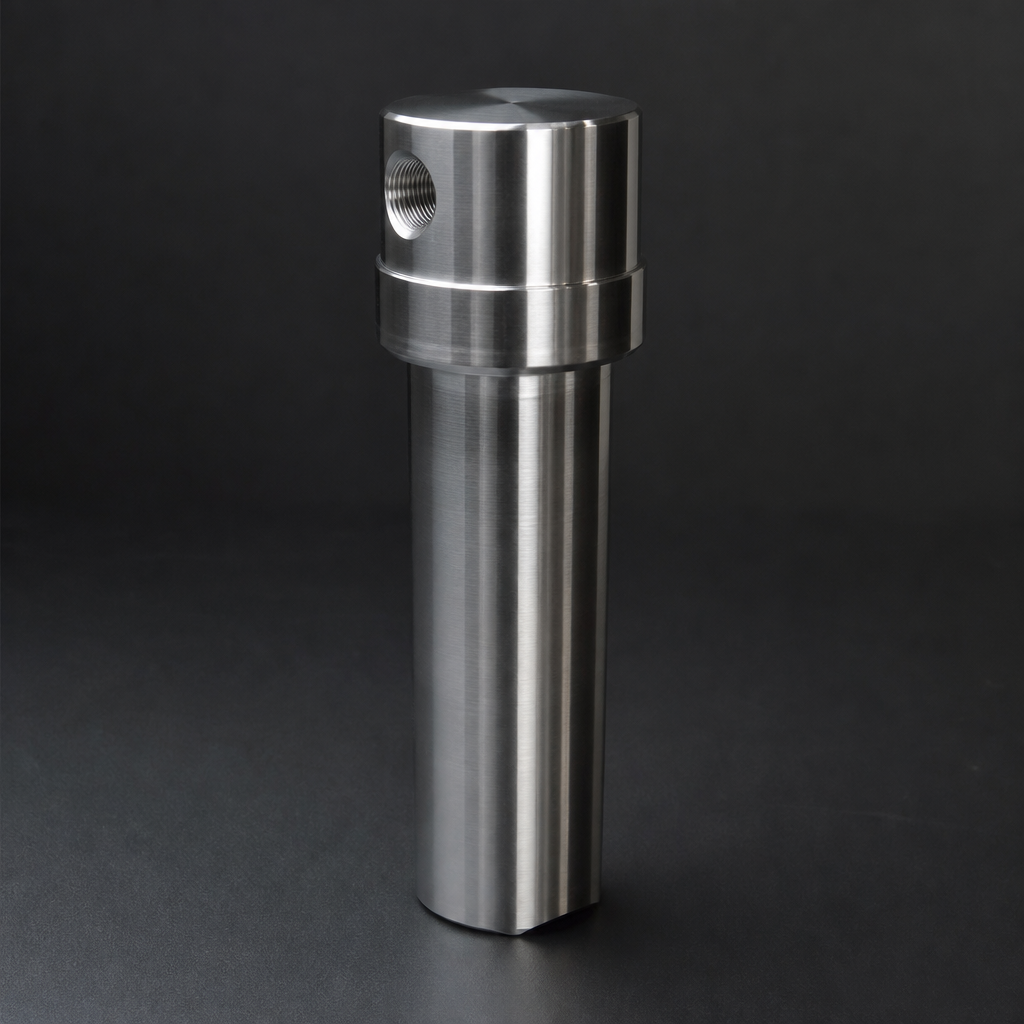
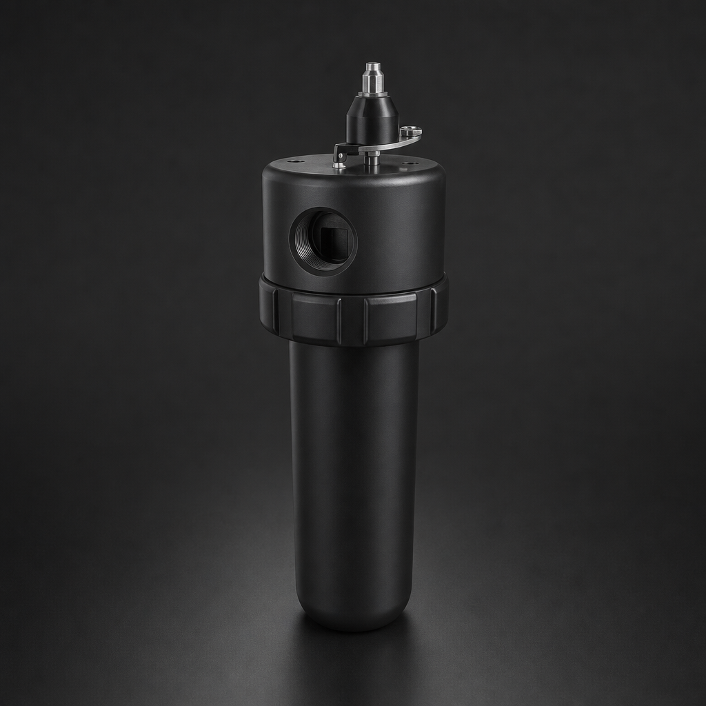
Breathing air systems typically operate at 7–30 bar, depending on whether they supply SCBA cylinders (200–300 bar fill pressure requires a booster) or direct-supply respirators (typically 6–8 bar). For the filtration train upstream of a booster or at point-of-use, R+F compressed air filter housings in the RF-H-310 to RF-H-395 series handle flows from a few Nm³/h for a single-user panel up to 12,000 Nm³/h for large industrial breathing air systems.
For higher-pressure applications — such as filtration at 100–250 bar downstream of a booster compressor — R+F process gas housings including the RF-H-150 (100 bar) and RF-H-160 (250 bar) provide the pressure rating and 316L stainless steel construction required for high-pressure breathing air service.
Seal material selection is also critical: EPDM seals are required for oxygen-enriched breathing air applications, while FKM/Viton seals are suitable for standard compressed air breathing systems up to 200 °C.
Documentation and Compliance Records
Both EN 12021 and OSHA 29 CFR 1910.134 require documented evidence of air quality. This means maintaining records of:
- Filter element change dates and batch numbers
- CO monitor calibration and alarm test records
- Periodic air quality test certificates from an accredited laboratory
- Compressor service records (oil type, change intervals)
A well-maintained breathing air system with a complete audit trail protects both workers and the organisation in the event of an incident investigation. R+F FilterElements can supply replacement elements with full traceability documentation to support your compliance records. Visit our contact page to discuss your breathing air filtration requirements with our engineering team.
- A standard industrial compressor delivers air that is contaminated with oil aerosols, water vapour, particulates, carbon monoxide from combustion, and hydrocarbon vapours from lubricants.
- A compliant breathing air system requires four sequential treatment stages.
- The tighter EN 12021 oil limit (0.
- CO monitor / catalytic converter:
Related Reading
- ISO 8573-1 Compressed Air Quality Classes Explained
- Coalescing vs Particulate Filter Elements — Which Do You Need?
- Oxygen Filtration Safety — What Every Engineer Must Know
Try our Engineering Sizing Tool → or discuss your requirements with our team.