Why sterile and high-purity filtration matters
In pharmaceutical manufacturing, semiconductor fabs, and food-grade processing, a single particle or colony-forming unit (CFU) in the process gas stream can render an entire batch worthless. Sterile and high-purity filtration goes far beyond standard particulate removal — it demands validated retention ratings, documented material traceability, and designs that withstand repeated sterilisation cycles without degrading.
The costs of failure are not just financial. A contaminated sterile gas supply in a parenteral drug facility can trigger FDA Form 483 observations, product recalls, or — in worst-case scenarios — patient harm. In semiconductor cleanrooms, a single 0.1 µm particle on a wafer can cause a circuit defect that cascades into yield losses worth thousands.
Key Takeaway
- Sterile-grade gas filters must achieve ≥ 10⁷ bacterial retention per cm² of filter area (ASTM F838-15).
- High-purity applications demand leak-tested housings, electropolished internals, and documented Ra ≤ 0.4 µm surface finishes.
- Every installation needs a validated integrity test (bubble point or diffusion) before and after each sterilisation cycle.
Particle classes and their real-world impact
Cleanroom classification standards such as ISO 14644-1 define maximum allowable particle concentrations by size. These classifications directly determine the filtration grade required for gases entering the controlled environment:
Separation mechanisms at the sub-micron scale
At the 0.2 µm level and below, standard depth filtration alone is insufficient. Sterile and high-purity filters rely on three overlapping mechanisms:
Sieve Retention
The primary mechanism for sterilising-grade membranes. Pores are smaller than the target organism (typically ≥ 0.2 µm for bacteria). The membrane physically blocks passage regardless of flow rate or loading.
Diffusional Interception
Particles below 0.1 µm undergo Brownian motion, causing them to wander into the fibre matrix. Residence time — and therefore filter depth — directly affects capture probability at this scale.
Electrostatic Adsorption
Charged PTFE or nylon membranes attract oppositely charged particles. This mechanism is especially relevant for sub-0.05 µm aerosols in semiconductor gas lines, though it can diminish after repeated steam-in-place (SIP) cycles.
Integrity testing is non-negotiable
A filter that passes a visual inspection may still have micro-defects invisible to the naked eye. Regulatory bodies (EU GMP Annex 1, FDA Guidance for Aseptic Processing) require a documented integrity test — typically a bubble-point or forward-flow diffusion test — before every use in sterile service.
Material selection: PTFE, stainless steel, or borosilicate?
The choice of filter medium depends on the gas, the sterilisation method, and the required particle retention:
- PTFE membranes — Hydrophobic, chemically inert, and available in absolute 0.01 to 0.2 µm ratings. Ideal for sterile venting, fermentation off-gas, and nitrogen blanketing. Withstand repeated autoclaving at 134 °C.
- Sintered stainless steel (316L) — For aggressive chemicals or high temperatures (> 200 °C). Standard ratings from 0.2 to 20 µm. Can be cleaned in place (CIP) and steam-sterilised indefinitely.
- Borosilicate microfibre — Achieves 99.9999 % DOP efficiency at 0.3 µm. Used in HEPA/ULPA-class gas filtration for cleanrooms. Not suitable for direct steam sterilisation.
In all cases, the housing must match the medium grade. An electropolished 316L housing with tri-clamp connections is standard for pharmaceutical service; a Ra ≤ 0.8 µm finish is typical for semiconductor applications, dropping to Ra ≤ 0.25 µm in ultra-high-purity (UHP) gas systems.
Regulatory reference
EU GMP Annex 1 (2022 revision) mandates that sterilising gas filters should be of 0.22 µm or less nominal pore size. Each filter must be integrity-tested before use, and test results must be documented as part of the batch record.
Pharmaceutical vs. semiconductor requirements
Although both sectors demand ultra-clean gas, their priorities diverge:
- Pharma: Focuses on microbial retention, endotoxin-free media, and documented validation (three successful consecutive process simulations). Filter elements must come with extractables/leachables data.
- Semiconductor: Prioritises sub-0.003 µm particle counts and metallic ion contamination below ppb levels. Gas-phase auto-particle counters (GPAC) verify filter performance in-line.
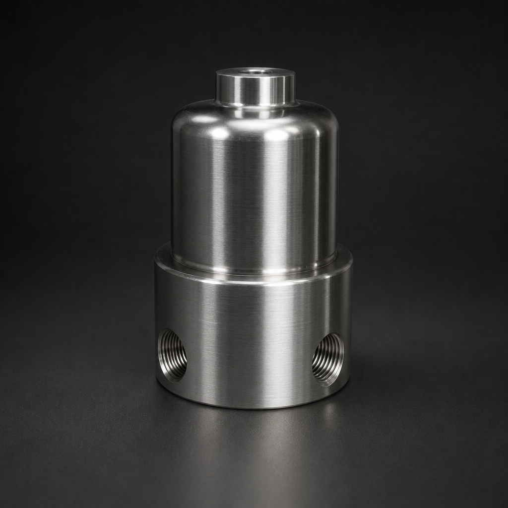
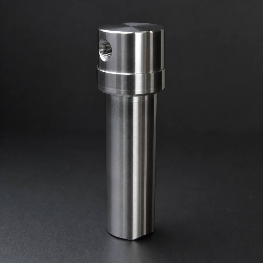
Both share a common demand: full lot traceability from raw material to installed element. Our RF-DIL inline filter series ships with a certificate of conformance that includes material heat numbers, weld records, and test results — meeting the documentation expectations of both industries.
Practical sizing for sterile gas filters
- Design flow velocity — Keep face velocity across the membrane below 5 cm/s for 0.2 µm PTFE elements to maintain rated retention.
- Service life target — 6 to 12 months between element changes in a well-maintained gas supply. Shorter if the upstream system lacks adequate pre-filtration.
- Allowable ΔP — Typically 10–50 mbar clean, with a change-out threshold of 150–200 mbar. Record differential pressure continuously for trend analysis.
Need help specifying a high-purity gas filter?
Use our Engineering Tool to model flow rates, pressure drops, and particle retention grades for your sterile or high-purity application. Or contact our team directly for project-specific guidance.
Five common mistakes in sterile gas filtration
- Skipping the pre-filter. A 1–5 µm coalescing or particulate pre-filter upstream of the sterile element dramatically extends its service life and reduces change-out frequency.
- Confusing nominal and absolute ratings. A “0.2 µm nominal” filter does not provide sterilising-grade retention. Always specify absolute ratings backed by bacterial challenge data.
- Using hydrophilic membranes on gas lines. Hydrophilic membranes wet-out and block gas flow when condensate is present. Use hydrophobic (PTFE) membranes for gas service, preceded by a coalescing filter if liquid carryover is possible.
- Ignoring housing dead-legs. Stagnant zones in the filter housing create condensation traps and potential microbial harbourage. Design housings with full-drain capability and no dead-leg exceeding 3 × pipe diameter.
- Failing to re-test integrity after thermal cycling. Repeated autoclaving can degrade seals and membrane structure. Integrity-test after every sterilisation cycle, not just on installation.
Recommended products
- Instrumentation & Inline Filters — Including the RF-DIL series for point-of-use sterile gas filtration.
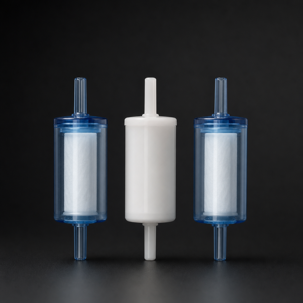
- Particulate Filter Elements — Pre-filtration stages to protect downstream sterile membranes.
- Coalescing Elements — Remove liquid aerosols before the sterile barrier to prevent membrane wetting.