
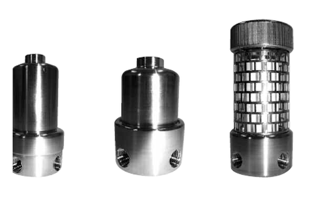
The challenge: flue gas after SCR is not a clean gas
The gas stream leaving an SCR catalyst may have 90–95% less NOx, but it is far from analyser-ready. A typical flue gas downstream of SCR contains:
- Fly ash and catalyst fines — particulate concentrations of 5–50 mg/m³, with particle sizes from sub-micron to 100 µm
- Residual ammonia — 2–50 ppm depending on SCR tuning, catalyst age, and load
- Ammonium salts — ammonium bisulphate (NH₄HSO₄) and ammonium sulphate ((NH₄)₂SO₄) form when ammonia reacts with SO₃ at temperatures below 300 °C
- Water vapour — typically 8–15 vol%, which must be removed before most analysers
- Acid gases — SO₂, HCl, HF at varying concentrations depending on fuel and scrubbing
Each of these contaminants creates specific problems for sample conditioning equipment and analysers. A robust sample path must handle all of them — in the right sequence.
The four-stage sample conditioning path
Reliable emission monitoring after SCR requires a systematic approach to sample conditioning. Each stage addresses a specific contaminant type, and the sequence matters — removing contaminants in the wrong order causes problems that are worse than the original contamination.
Stage 1: High-temperature particulate removal
A heated probe filter (sintered metal or ceramic, typically 2–10 µm) at process temperature removes fly ash and catalyst fines. This filter must operate above the acid dew point (typically > 160 °C for sulphur-bearing fuels) to prevent condensation and corrosion.
Stage 2: Ammonia removal (acid wash)
An acid wash filter element neutralises residual ammonia via reaction with phosphoric acid. This step MUST come before cooling — at lower temperatures, ammonia reacts with SO₃ to form ammonium bisulphate, which blocks coolers, sample lines, and downstream filters.
Stage 3: Sample cooling and moisture removal
A Peltier cooler or refrigeration dryer reduces the sample to 2–5 °C, condensing water and heavy hydrocarbons. With ammonia already removed, there is no risk of ammonium salt precipitation in the cooler.
Stage 4: Final fine filtration
A borosilicate microfibre or PTFE membrane element (0.01–1 µm) provides the last particle barrier before the analyser. This catches any condensate droplets, salt crystals, or fine particulate that survived the upstream stages.
Stage 1: Getting particulate removal right
The probe filter is the first line of defence and takes the heaviest abuse. In SCR applications, it must handle not just fly ash but also catalyst fines — small fragments of the SCR catalyst that break off during thermal cycling or from ammonia salt deposits on the catalyst surface.
Key selection criteria:
- Material: Sintered stainless steel (316L or Hastelloy) for most fuels; sintered ceramic for high-chloride or high-fluoride environments
- Pore size: 2–10 µm — fine enough to protect downstream elements, coarse enough to avoid rapid blocking
- Temperature rating: Must exceed the maximum expected gas temperature, including transient conditions during start-up
- Blow-back capability: In high-dust applications, automatic blow-back with compressed air or nitrogen extends filter life significantly
Sintered element sizing
R+F FilterElements sintered stainless steel elements (RF-SS series) and sintered PTFE elements (RF-TF series) are available in sizes from Ø12 × 32 mm to Ø25 × 178 mm. For SCR probe applications, the Ø25 × 64 mm size provides the best balance between capacity and response time.
Stage 2: Why ammonia must be removed before cooling
This is the most common mistake in SCR sample conditioning — and the most expensive one. When ammonia-laden gas is cooled below approximately 150 °C in the presence of SO₃, ammonium bisulphate (NH₄HSO₄) forms:
NH₃ + SO₃ + H₂O → NH₄HSO₄
Ammonium bisulphate is a sticky, hygroscopic substance that deposits on every surface it contacts — sample lines, cooler internals, filter elements, and analyser cells. It is extremely difficult to remove (requiring hot water washing or replacement of affected components) and is the single most common cause of CEMS downtime in SCR-equipped plants.
Key Takeaway
Stage 3: Sample cooling — the details that matter
With ammonia removed, the cooler stage becomes straightforward. Key considerations:
- Cooler type: Peltier (thermoelectric) coolers are standard for single-stream systems; compressor coolers for multi-stream or high-flow applications
- Dew point: Target 2–5 °C for CLD/NDIR analysers; some applications tolerate higher temperatures
- Condensate drainage: Must be continuous and automatic — a blocked peristaltic pump or float drain quickly floods the cooler
- Material: Glass or PTFE-lined cooler tubes for SO₂/HCl-bearing gases; stainless steel is acceptable for low-acid-gas applications
Stage 4: The last line of defence
The final filter element protects the analyser from any remaining contamination — condensate droplets re-entrained from the cooler, sub-micron particulate that passed the probe filter, or fine salt crystals that form during cooling.
For CLD and NDIR analysers, a borosilicate glass microfibre element with 99.99% efficiency at 0.01 µm is the standard choice. The element should be housed in a compact inline or panel-mount housing close to the analyser, with easy access for replacement.
Common pitfalls in SCR sample conditioning
| Problem | Root Cause | Solution |
|---|---|---|
| Cooler blocks every 2–4 weeks | Ammonium bisulphate deposits from unconditioned NH₃ | Install acid wash element upstream of cooler |
| NOx readings 5–15% too high | NH₃ oxidised to NO in CLD converter | Acid wash element before converter |
| Rapid probe filter blocking | Ammonium salt formation on filter at intermediate temperatures | Heat trace sample line, keep probe > acid dew point |
| Drifting SO₂ readings | NH₃ absorbing SO₂ in wet sample path | Remove NH₃ before moisture removal stage |
| Analyser cell contamination | Insufficient final filtration after cooler | Install 0.01 µm borosilicate element before analyser |
Element selection summary
A complete sample conditioning path for SCR emission monitoring uses three types of R+F FilterElements products:
- Stage 1 — Probe filter: RF-SS or RF-TF sintered elements (2–10 µm) for bulk particulate removal at process temperature
- Stage 2 — Ammonia removal: RF-AW acid wash elements — K-type (PVDF, ≤ 150 °C) or S-type (silica, ≤ 480 °C) depending on extraction temperature
- Stage 4 — Final filter: RF-C coalescing or RF-P particulate elements (0.01 µm) in an RF-H-170 or RF-H-137G housing at the analyser
Need help specifying the complete sample path?
R+F FilterElements can configure the full filter chain for your SCR emission monitoring application — from probe to analyser. Send us your process data and we will provide a detailed recommendation.

