
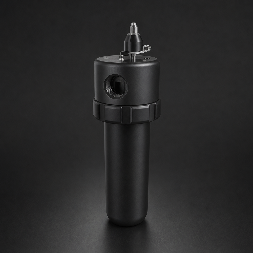
When a coalescing filter is asked to handle both bulk liquid slugs and fine aerosol mist simultaneously, it rarely performs well at either task. The solution is a two-stage approach: a catchpot or drain vessel upstream to knock out the bulk liquid, followed by a properly sized coalescing element to capture the remaining aerosol. This guide explains how catchpots work, the drain options available, and how to integrate them with R+F coalescing filter housings.
What Is a Catchpot?
A catchpot (also called a bulk liquid separator or knock-out pot) is a simple pressure vessel installed upstream of a coalescing filter. Its purpose is to remove free liquid — water, oil, or condensate — that travels as slugs or large droplets in the gas stream. Unlike a coalescing element, a catchpot relies on gravity and momentum change rather than filtration media. Gas enters, velocity drops as the cross-section increases, and liquid falls to the bottom of the vessel where it is collected and drained.
Catchpots are particularly important in compressed air systems where:
- Intercooler condensate has not been fully removed
- Long horizontal pipe runs accumulate pooled liquid
- Seasonal temperature swings cause heavy condensation
- Compressor oil carry-over is significant
For compressed air applications, the R+F compressed air filter range includes housings designed to work in series with upstream catchpots. The RF-H-310 to RF-H-395 series aluminium housings accept both RF-C coalescing elements and RF-P particulate elements, making them ideal as the second stage after bulk liquid removal.
Direct-Mount vs Valve-Isolated Drain Vessels
The drain vessel configuration determines how liquid is removed from the catchpot and how easily the system can be serviced. There are two principal arrangements:
Direct-Mount Drain Vessels
A direct-mount drain vessel is bolted directly to the bottom outlet of the filter housing or catchpot body. There is no isolation valve between the vessel and the main pressure boundary. This arrangement is compact and low-cost, but it means the entire system must be depressurised to service or replace the drain vessel. Direct-mount designs are common on smaller compressed air systems where downtime is acceptable.
Valve-Isolated Drain Vessels
A valve-isolated drain vessel incorporates a manual or automatic isolation valve between the catchpot body and the drain vessel. This allows the drain vessel to be removed, cleaned, or replaced under pressure — a significant advantage in continuous-process applications. The isolation valve also provides a secondary containment boundary, which is important when the collected liquid is hazardous (e.g. compressor oil, glycol, or process condensate).
Drain Types: Manual, Automatic Float, and Continuous
Once liquid has collected in the catchpot or drain vessel, it must be removed. Three drain types are commonly used, each with distinct advantages:
Manual Drains
A simple ball valve or needle valve at the bottom of the catchpot. The operator opens the valve periodically to purge collected liquid. Manual drains are reliable and inexpensive but depend entirely on operator discipline. If draining is neglected, liquid backs up into the coalescing element — exactly the problem the catchpot was installed to prevent.
Automatic Float Drains
A float mechanism rises with the liquid level and opens a drain valve when a set level is reached. No electrical power is required. Float drains are the most common automatic option for compressed air systems. Their weakness is susceptibility to fouling: oil-contaminated condensate can coat the float and prevent it from rising, causing the drain to stick closed. Regular inspection is essential.
Continuous (Timed) Drains
A solenoid valve opens on a fixed time cycle — for example, 5 seconds every 30 minutes — regardless of actual liquid level. Continuous drains are simple and reliable but waste compressed air during each purge cycle. They are best suited to high liquid-load applications where the drain interval can be tuned to match actual condensate production.
Zero-Loss Electronic Drains
An electronic level sensor detects liquid accumulation and opens a solenoid valve only when liquid is present. No compressed air is wasted. Zero-loss drains are the most energy-efficient option and are increasingly specified on larger compressed air systems where energy costs are significant.
Need help selecting the right catchpot and coalescing filter combination?
Sizing a Catchpot for Your System
Catchpot sizing depends on three factors: gas flow rate (Nm³/h), operating pressure (bar g), and expected liquid load (litres per hour). The vessel must be large enough that gas velocity inside the pot drops below the terminal settling velocity of the largest liquid droplets — typically below 0.3 m/s for water droplets in compressed air at 7 bar g.
For most compressed air applications, a catchpot with a cross-sectional area giving a gas velocity of 0.1–0.2 m/s is sufficient. At higher pressures (above 20 bar g), the increased gas density means smaller droplets settle more readily, and a smaller vessel may suffice.
The RF-H-310 to RF-H-395 series housings cover flow rates from 50 to 12,000 Nm³/h at up to 17 bar. For higher-pressure applications — natural gas, hydrogen, or instrument air — the RF-H-150 process gas housing (rated to 100 bar) provides a compact, 316L stainless steel solution that can be configured as a catchpot or as a coalescing filter stage.
Use our free Engineering Tool to get a filtration recommendation for your specific application in under 2 minutes.
Drain Vessel Comparison
| Feature | Direct-Mount | Valve-Isolated |
|---|---|---|
| Serviceability under pressure | No — system must be depressurised | Yes — isolation valve allows hot-swap |
| Cost | Lower | Higher (valve + fittings) |
| Hazardous liquid suitability | Not recommended | Suitable with correct valve selection |
| Footprint | Compact | Larger (valve adds height) |
| Typical application | Workshop air, small compressor rooms | Process gas, continuous production |
Integrating Catchpots with R+F Coalescing Filter Housings
The most effective compressed air filtration trains combine a catchpot with a downstream coalescing filter. A typical arrangement for a 7 bar compressed air system might be:
- Catchpot with automatic float drain — removes bulk liquid slugs and large droplets
- RF-H-385AI with RF-C-51476 coalescing element — captures aerosol to <0.01 mg/m³ residual oil
- RF-H-385AI with RF-P-51476 particulate element — removes downstream particulate to 0.3 µm
For higher-purity requirements — instrument air, food-grade CO₂, or pharmaceutical nitrogen — an RF-DIL inline filter at the point of use provides a final polishing stage. The RF-DIL is a disposable, direct-mount filter that requires no housing and is replaced as a complete unit, making it ideal for critical point-of-use applications.
Where activated carbon removal of residual hydrocarbon vapour is required, an RF-AC adsorption element can be fitted in a third housing stage downstream of the coalescing filter. This combination achieves ISO 8573-1 Class 1 oil content (<0.01 mg/m³) when correctly sized. See our guide to coalescing vs particulate filter elements for more detail on element selection.
For process gas applications at higher pressures, the RF-H-150 compact process gas housing (100 bar, 316L stainless steel) can be configured as a two-stage train — catchpot followed by coalescing filter — in a minimal footprint. This is particularly useful in skid-mounted gas conditioning systems where space is at a premium. Learn more about ISO 8573-1 compressed air quality classes and how they apply to your system design.
Maintenance Considerations
A catchpot that is not drained regularly becomes a liquid reservoir that eventually floods the downstream coalescing filter. Establish a maintenance schedule based on actual condensate production — which varies significantly with ambient temperature, compressor load, and inlet air humidity. In humid climates or during summer months, daily draining may be necessary. In dry conditions, weekly draining may suffice.
Inspect float drains quarterly for fouling. Test manual drains monthly. For zero-loss electronic drains, verify sensor function annually and check solenoid valve operation. Keep a log of drain intervals and liquid volumes — a sudden increase in condensate production often indicates a compressor fault (e.g. failing intercooler, worn piston rings) that should be investigated before it causes downstream damage.
- A catchpot (also called a bulk liquid separator or knock-out pot) is a simple pressure vessel installed upstream of a coalescing filter.
- The drain vessel configuration determines how liquid is removed from the catchpot and how easily the system can be serviced.
- Once liquid has collected in the catchpot or drain vessel, it must be removed.
- Catchpot sizing depends on three factors: gas flow rate (Nm³/h), operating pressure (bar g), and expected liquid load (litres per hour).
Related Reading
- Coalescing vs Particulate Filter Elements — Which Do You Need?
- ISO 8573-1 Compressed Air Quality Classes Explained
- How Coalescing Filters Work — The Science Behind Aerosol Removal
Try our Engineering Sizing Tool → or discuss your requirements with our team.

