When liquid aerosols contaminate a process gas stream — whether oil mist from a compressor, water droplets from a cooler, or hydraulic fluid carried over from a pump — the consequences range from instrument fouling and catalyst poisoning to product contamination and regulatory non-compliance. Coalescing filtration is the engineering solution, and the choice of filter medium determines whether you achieve parts-per-billion cleanliness or merely marginal improvement. This article explains the physics behind borosilicate microfibre coalescers, why they outperform alternative media, and how to select the right R+F element for your application.
Why Liquid Aerosols Are Difficult to Remove
Liquid aerosols in gas streams exist as sub-micron droplets — typically 0.01 µm to 5 µm in diameter — suspended by Brownian motion and gas velocity. At these sizes, gravity has negligible effect; the droplets follow gas streamlines and pass straight through coarse filter media. A standard particulate filter with 1 µm rating will capture solid particles efficiently but allow liquid aerosols to penetrate, because the droplets deform and squeeze through pores under differential pressure.
The challenge is compounded by the fact that oil aerosols from rotary screw compressors are polydisperse — they span a wide size range, with the most penetrating particle size (MPPS) typically around 0.1–0.3 µm. Any coalescing element must perform across this entire spectrum to deliver consistent downstream cleanliness.
The Three Capture Mechanisms in Borosilicate Microfibre Media
Borosilicate glass microfibre media captures aerosol droplets through three distinct physical mechanisms, each dominant at a different particle size range. Understanding these mechanisms explains why fibre diameter, packing density, and bed depth all matter critically in coalescer design.
1. Brownian Diffusion (Sub-Micron Droplets, < 0.3 µm)
Droplets smaller than approximately 0.3 µm are so light that random thermal collisions with gas molecules cause them to deviate from streamlines — a phenomenon known as Brownian motion. This random walk increases the probability that a droplet will contact a fibre surface. Fine borosilicate fibres (0.1–1 µm diameter) maximise this effect: their small diameter creates a high specific surface area per unit volume, and their close spacing means a diffusing droplet rarely travels far before encountering a fibre. Capture efficiency by diffusion increases as particle size decreases and as gas velocity decreases — the opposite of inertial mechanisms.
2. Interception (Mid-Range Droplets, 0.3–1 µm)
Droplets in the 0.3–1 µm range follow gas streamlines closely but are large enough that their physical radius brings them into contact with fibres even when their centre follows the streamline. This is direct interception — no deviation from the streamline is required. Interception efficiency scales with the ratio of droplet diameter to fibre diameter, which is why fine fibres (0.1–3 µm) are so effective: the ratio is favourable across the entire mid-range.
3. Inertial Impaction (Larger Droplets, > 1 µm)
Droplets larger than approximately 1 µm have sufficient mass that they cannot follow rapid changes in gas streamline direction around a fibre. Their inertia carries them forward onto the fibre surface. Impaction efficiency increases with droplet size and gas velocity. In a well-designed coalescer, larger droplets are captured near the upstream face of the medium, while sub-micron droplets penetrate deeper before being captured by diffusion.
Why Borosilicate Glass Fibres Are the Optimal Medium
Not all fibres are equal. Borosilicate glass microfibres have a unique combination of properties that make them the preferred medium for liquid aerosol coalescence in demanding process gas applications.
High surface area per unit volume. Fibres in the 0.1–3 µm diameter range pack an enormous surface area into a small volume. A single cubic centimetre of borosilicate microfibre medium may contain several kilometres of fibre length, providing abundant capture sites for diffusing and intercepting droplets.
Controlled wettability. Borosilicate glass has a naturally oleophilic (oil-wetting) surface. Once a droplet contacts a fibre, it spreads into a thin film rather than beading up. This film formation is the first step in coalescence — without it, captured droplets would re-entrain into the gas stream under differential pressure.
Graduated density structure. High-performance coalescing elements use a graded-density construction: coarser fibres (2–3 µm) on the upstream face capture larger droplets by impaction, while progressively finer fibres (0.1–0.5 µm) in the interior capture sub-micron aerosols by diffusion. This gradient prevents premature blinding of the fine inner layers and extends service life.
Chemical and thermal stability. Borosilicate glass is inert to virtually all process gases, oils, and solvents encountered in industrial filtration. Standard RF-C elements are rated to 100 °C; S-type variants extend this to 200 °C for high-temperature applications such as vacuum pump exhaust or hot compressed air systems. See the full R+F filter element range for available grades.
Stage 2 — Film formation and spreading.
The Coalescence Process: From Capture to Drainage
Capturing a droplet is only the first step. The coalescing element must then convert millions of captured micro-droplets into large, drainable droplets that fall by gravity to the sump. This four-stage process is what distinguishes a true coalescer from a simple depth filter.
Stage 1 — Capture. Droplets are captured on fibre surfaces by the three mechanisms described above. The captured liquid forms a thin wetting film on the fibre.
Stage 2 — Film formation and spreading. The wetting film spreads along the fibre length. Where fibres cross or touch, liquid accumulates at the contact point, forming a liquid bridge.
Stage 3 — Droplet growth. Liquid bridges grow as more droplets are captured and liquid migrates along fibres. Eventually, the accumulated liquid forms a droplet large enough to be visible — typically 0.5–2 mm in diameter.
Stage 4 — Gravity drainage. Once a droplet exceeds the critical size at which gravity overcomes surface tension and gas drag, it detaches from the fibre and drains downward through the element to the housing sump. From there, it is discharged via an automatic drain.
Use our free Engineering Tool to get a filtration recommendation for your specific application in under 2 minutes.
Depth-Loaded Borosilicate vs Pleated Media: Why Structure Matters
Pleated filter media — whether glass fibre, cellulose, or synthetic — are excellent for particulate removal but fundamentally unsuited to liquid aerosol coalescence. The reason lies in the coalescence mechanism itself.
In a pleated element, the medium is thin (typically 0.5–2 mm) and the flow path through the medium is short. Captured droplets form films on the upstream face but have insufficient bed depth to coalesce into drainable droplets before the gas flow re-entrains them. The result is a fine mist of re-entrained droplets on the downstream side — often smaller than the original aerosol, because the pleated medium has broken up larger droplets into finer ones.
Depth-loaded borosilicate elements, by contrast, provide a bed depth of 10–30 mm. Droplets captured near the upstream face have time and space to coalesce as they migrate through the medium under the combined influence of gas flow and capillary forces. By the time liquid reaches the downstream face, it has formed large droplets that drain cleanly. This is why coalescing elements differ fundamentally from particulate elements in both construction and performance.
| Parameter | Depth-Loaded Borosilicate | Pleated Glass Fibre |
|---|---|---|
| Bed depth | 10–30 mm | 0.5–2 mm |
| Coalescence mechanism | Full 4-stage (capture → film → growth → drain) | Capture only; re-entrainment likely |
| Residual oil (HE grade) | < 0.01 mg/m³ | 0.1–1 mg/m³ (typical) |
| Suitable for liquid aerosols | Yes — primary application | No — risk of re-entrainment |
| ISO 8573-1 Class 1 oil | Achievable (with activated carbon stage) | Not achievable alone |
R+F Coalescing Element Grades and Performance Data
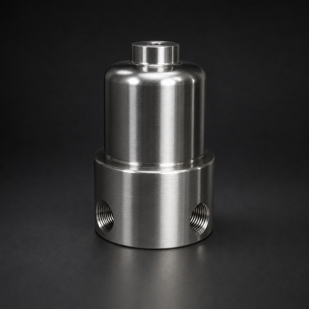
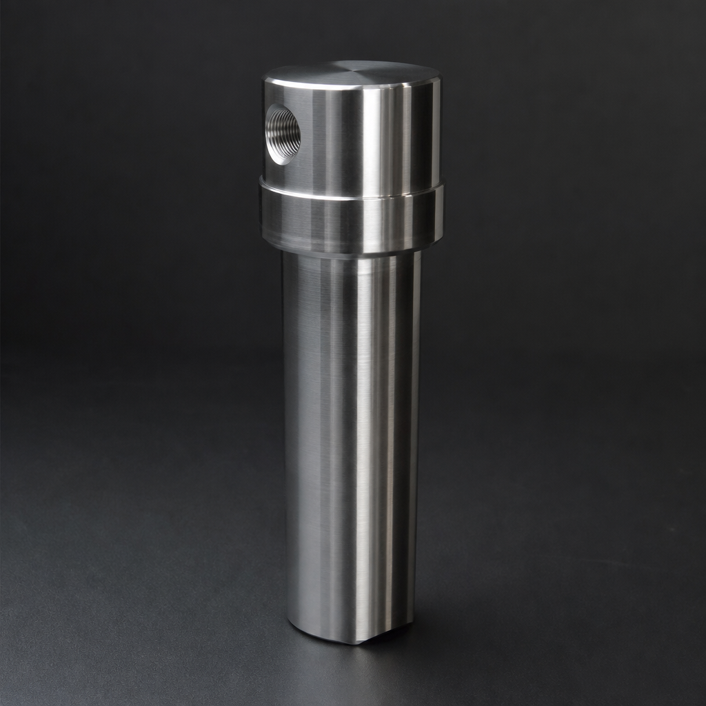
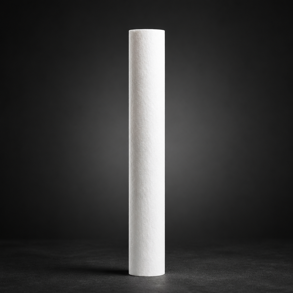
R+F FilterElements offers its own range of borosilicate microfibre coalescing elements in four efficiency grades, covering applications from general compressed air treatment to ultra-clean process gas and hydrogen purification. All elements are available from R+F branded stock for the RF-H housing series.
The RF-C coalescing element series is the core product for liquid aerosol removal. Available in six standard sizes (12032, 12057, 25064, 25178, 51230, 51476), these elements fit directly into the RF-H-310 to RF-H-395 compressed air filter housings and the RF-H-150 process gas housing. For applications requiring both liquid aerosol removal and residual oil vapour adsorption, the RF-C element is paired with an RF-AC activated carbon stage downstream.
Efficiency grades available from R+F FilterElements:
- PF (Pre-Filter): Bulk liquid and coarse aerosol removal; residual oil < 5 mg/m³. Used as a pre-stage to protect fine coalescing elements from liquid slugs.
- ST (Standard): General-purpose coalescing; residual oil < 1 mg/m³. Suitable for most compressed air applications where ISO 8573-1 Class 3 or 4 oil is acceptable.
- ME (Medium Efficiency): Residual oil < 0.1 mg/m³; ISO 8573-1 Class 2 oil. For instrument air, food-grade applications, and process gas streams requiring moderate cleanliness.
- HE (High Efficiency): Residual oil < 0.01 mg/m³; ISO 8573-1 Class 1 oil. For semiconductor, pharmaceutical, and analytical instrument applications where contamination is critical. The RF-C HE grade achieves 99.99% efficiency at ≥ 0.1 µm.
For high-pressure process gas applications — natural gas metering, hydrogen compression, or analyser sample conditioning — the RF-C elements are available in K-type (sour gas / H₂S resistant) and S-type (200 °C rated) variants. Consult the ISO 8573-1 compressed air quality guide to determine which grade your application requires.
- Liquid aerosols in gas streams exist as sub-micron droplets — typically 0.
- Borosilicate glass microfibre media captures aerosol droplets through three distinct physical mechanisms, each dominant at a different particle size range.
- High surface area per unit volume.
- Stage 2 — Film formation and spreading.
Selecting the Right Coalescing Element
Correct element selection requires matching four parameters: flow rate (Nm³/h), operating pressure (bar g), temperature (°C), and required downstream cleanliness (ISO 8573-1 class). Oversizing a coalescer reduces gas velocity through the medium, which impairs inertial impaction of larger droplets and can cause liquid flooding of the element. Undersizing increases differential pressure, shortens service life, and risks re-entrainment.
R+F FilterElements provides a sizing tool that calculates the correct housing and element combination for your operating conditions. For process gas applications with unusual contaminants — glycol, amine, hydraulic fluid — contact the engineering team to confirm compatibility with the borosilicate binder and seal materials.
Try our Engineering Sizing Tool → or discuss your requirements with our team.