
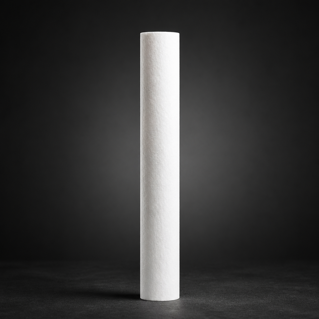
Choosing the wrong filter medium is one of the most common — and costly — mistakes in process gas and compressed air system design. Glass fibre, PTFE, sintered metal, and activated carbon each behave very differently under pressure, temperature, and chemical exposure. Understanding those differences before specifying a filter element can prevent premature failure, contamination breakthroughs, and unplanned downtime.
This guide compares the four principal filter media types available from R+F FilterElements, covering how each works, what it removes, its temperature and chemical limits, and which applications it suits best.
1. Glass Fibre (Borosilicate Microfibre)
Borosilicate glass microfibre is the workhorse of industrial gas filtration. Fibres are drawn to sub-micron diameters and bonded into a depth-loading matrix that captures both solid particles and liquid aerosols through a combination of inertial impaction, interception, and diffusion.
R+F coalescing elements (RF-C series) and particulate elements (RF-P series) are built on borosilicate microfibre. The RF-C elements achieve 99.99% efficiency at ≥ 0.1 µm for liquid aerosols, making them the standard choice for oil-mist removal in compressed air systems and instrument gas supply lines. RF-P elements target solid particulate at ≥ 0.3 µm with the same 99.99% efficiency rating.
Temperature limits: Standard glass fibre elements operate to 100 °C. S-type variants extend this to 200 °C, suitable for hot compressed air or steam-laden streams.
Chemical compatibility: Borosilicate glass is inert to most hydrocarbons, alcohols, and neutral gases. It is not suitable for strong alkalis (pH > 10) or hydrofluoric acid, which attack the silica matrix.
Best for: Compressed air, nitrogen, natural gas, instrument gas — wherever liquid aerosol or fine particulate removal is the primary objective.
2. PTFE (Polytetrafluoroethylene) Membrane
PTFE membrane filtration works on a fundamentally different principle: size exclusion through a tortuous pore structure rather than depth loading. The membrane presents an absolute barrier — particles larger than the rated pore size cannot pass, regardless of flow velocity or loading history.
R+F offers PTFE hydrophobic membrane technology in the RF-GMS-170 membrane separator. The hydrophobic surface repels liquid water and aqueous solutions while allowing gas to pass freely, making it ideal as a liquid barrier in sample conditioning and analyser protection circuits.
Temperature limits: PTFE is stable from –200 °C to +260 °C, far exceeding glass fibre in both cryogenic and high-temperature service.
Chemical compatibility: PTFE is chemically inert to virtually all industrial gases, acids, alkalis, and solvents — including hydrofluoric acid, chlorine, and aggressive process gases where glass fibre would degrade. This makes it the preferred medium for hydrogen service, oxygen systems, and corrosive gas streams.
Best for: Absolute liquid barriers, corrosive gas filtration, oxygen service, cryogenic applications, and any duty where chemical attack on the medium is a concern.
3. Sintered Metal
Sintered metal elements are manufactured by compacting and heat-fusing metal powder — typically 316L stainless steel, Hastelloy, or Inconel — into a rigid, self-supporting structure. The interconnected pore network provides mechanical strength that no fibrous medium can match.
R+F sintered metal elements are available for high-temperature and high-pressure duties, rated to 450 °C and compatible with the RF-H-150 and RF-H-160 process gas housings. They are cleanable by back-flushing, ultrasonic cleaning, or chemical regeneration, making them cost-effective in high-loading applications where disposable elements would require frequent replacement.
Temperature limits: Up to 450 °C depending on alloy selection — the highest of any medium type discussed here.
Chemical compatibility: Determined by the alloy chosen. 316L stainless steel handles most process gases, acids, and alkalis. Hastelloy C-276 extends compatibility to chlorine, wet HCl, and highly oxidising environments.
Best for: High-temperature process gas, catalyst protection, hot gas filtration, applications requiring cleanable/regenerable elements, and duties where mechanical robustness is paramount.
Stage 3 — Adsorption filter (RF-AC or RF-DIA):
4. Activated Carbon
Activated carbon operates by adsorption rather than mechanical filtration. Contaminant molecules are attracted to and held on the vast internal surface area of the carbon granules — typically 800–1,200 m² per gram. This makes it uniquely effective at removing vapour-phase contaminants that pass straight through any mechanical filter.
R+F adsorption elements (RF-AC series) and disposable inline adsorbers (RF-DIA) target residual oil vapour, odours, and trace hydrocarbons. The RF-AC elements reduce residual oil content to below 0.003 mg/m³ — meeting ISO 8573-1 Class 1 for total oil. They are always installed downstream of a coalescing pre-filter (RF-C) to prevent liquid oil from saturating the carbon bed prematurely.
Temperature limits: Activated carbon elements are typically rated to 60–70 °C. Elevated temperatures reduce adsorption capacity and can cause desorption of previously captured contaminants.
Chemical compatibility: Carbon is broadly compatible with dry gases but should not be used with strong oxidisers (ozone, chlorine dioxide) which can ignite the carbon bed. Moisture reduces adsorption efficiency significantly.
Best for: Oil vapour removal, odour control, trace hydrocarbon reduction, food and beverage gas quality, and any application requiring ISO 8573-1 Class 1 oil content.
Use our free Engineering Tool to get a filtration recommendation for your specific application in under 2 minutes.
Performance at a Glance
Filter Media Selection Guide
| Medium | Mechanism | Max Temp | Removes | Typical R+F Element | Regenerable |
|---|---|---|---|---|---|
| Glass fibre (borosilicate) | Depth loading — impaction, interception, diffusion | 100 °C (200 °C S-type) | Liquid aerosols, solid particles ≥ 0.1 µm | RF-C, RF-P | No |
| PTFE membrane | Size exclusion — absolute pore barrier | 260 °C | Liquid water, particles above pore rating | RF-GMS-170 | Limited |
| Sintered metal (316L SS) | Depth/surface filtration — rigid pore matrix | 450 °C | Solid particles, catalyst fines | RF-H-150 / RF-H-160 compatible | Yes |
| Activated carbon | Adsorption — molecular surface attraction | 60–70 °C | Oil vapour, odours, trace hydrocarbons | RF-AC, RF-DIA | No |
Combining Media Types in a Filter Train
Most real-world applications require more than one medium. A well-designed filter train sequences media types to protect each stage from the contaminants that would damage or saturate it:
- Stage 1 — Particulate pre-filter (RF-P): Removes bulk solid particles and protects downstream coalescing elements from premature blinding.
- Stage 2 — Coalescing filter (RF-C): Removes liquid aerosols and fine particulate to 0.1 µm. This is the primary protection stage for most compressed air and process gas systems.
- Stage 3 — Adsorption filter (RF-AC or RF-DIA): Removes residual oil vapour and odours. Must always follow a coalescing stage — liquid oil will saturate the carbon bed in minutes.
- Stage 4 — PTFE membrane or sintered metal (application-specific): Provides an absolute liquid barrier or high-temperature particulate removal where the duty demands it.
For natural gas and biogas applications, the filter train design must also account for H₂S, moisture, and heavy hydrocarbon condensates — contaminants that can interact with the filter medium and affect both efficiency and service life. Consult the ISO 8573-1 quality class guide to establish the target cleanliness level before selecting media.
For point-of-use protection in instrument and analyser circuits, the compact RF-DIL disposable inline filter provides a convenient last-line-of-defence particulate barrier without requiring a full housing assembly.
- Chemical compatibility:
- Chemical compatibility:
- Chemical compatibility:
- Chemical compatibility:
Related Reading
- Coalescing vs Particulate Filter Elements — Which Do You Need?
- ISO 8573-1 Compressed Air Quality Classes Explained
- Filtration Requirements for Hydrogen Electrolysis Systems
Try our Engineering Sizing Tool → or discuss your requirements with our team.

