
Why Fuel Cell Stacks Fail Prematurely — and What the Hydrogen Supply Has to Do With It
Proton exchange membrane (PEM) fuel cells are among the most promising technologies for clean power generation, yet they remain surprisingly fragile when it comes to the quality of the hydrogen they consume. Engineers who have witnessed a stack degradation event first-hand will recognise the pattern: performance drops gradually, then sharply, and post-mortem analysis almost always reveals contamination as a root cause. The culprit is rarely the membrane chemistry itself — it is what arrives with the hydrogen.
Understanding the contamination mechanisms at play, and specifying the correct fuel cell inlet filter for each stage of the supply chain, is the most reliable way to protect your investment and keep a stack running at rated output for its full design life.
The Two Contamination Pathways That Destroy PEM Membranes
1. Particulate Damage — Physical Perforation of the Membrane
A PEM membrane is typically between 15 µm and 175 µm thick, depending on the product grade. Particles larger than approximately 5 µm that reach the membrane electrode assembly (MEA) can become embedded in or puncture the membrane during compression and operation. The consequences are severe:
- Gas crossover: Hydrogen migrates from the anode to the cathode side, reacting directly with oxygen and generating localised heat that accelerates membrane degradation.
- Short-circuit risk: Conductive particles — metal swarf, pipe scale, or carbon fines — can bridge the membrane and cause electrical shorts within the stack.
- Irreversible pinhole formation: Once a pinhole forms, it grows under the mechanical stress of pressure cycling, ultimately rendering the affected cell unusable.
Particle contamination typically originates from the hydrogen production and compression infrastructure: compressor wear debris, pipeline scale, valve seat erosion, and particulate carry-over from storage vessels. Even a newly commissioned system can shed significant particulate during the first hours of operation.
2. Ionic Contamination — Catalyst Poisoning by Trace Metals
The second contamination pathway is less visible but equally destructive. Trace metal ions — most commonly iron (Fe²⁺/Fe³⁺) and copper (Cu²⁺) — enter the hydrogen stream through corrosion of carbon steel pipework, brass fittings, and uncoated compressor components. Once inside the stack, these ions:
- Displace protons in the ionomer: Metal cations have a higher affinity for the sulphonate groups in Nafion-type membranes than hydrogen ions do, reducing proton conductivity and increasing membrane resistance.
- Generate hydroxyl radicals via Fenton chemistry: Iron ions catalyse the decomposition of hydrogen peroxide (a by-product of oxygen reduction) into highly reactive hydroxyl radicals that attack the polymer backbone of the membrane.
- Poison the platinum catalyst: Copper ions deposit preferentially on platinum active sites, reducing the electrochemically active surface area and permanently lowering cell voltage.
Unlike particulate damage, ionic contamination is cumulative and largely irreversible. A stack exposed to even parts-per-billion levels of Fe or Cu over thousands of operating hours will show measurable performance loss that cannot be recovered by flushing or conditioning.
What the Standards Say About Hydrogen Fuel Quality
ISO 14687:2019 defines the hydrogen fuel quality requirements for PEM fuel cell road vehicles, and its limits are instructive for stationary applications as well. The standard specifies a maximum total particulate concentration of 1 mg/kg with a maximum particle size of 10 µm, and sets ionic contaminant limits in the low parts-per-billion range. Meeting these targets in a real-world hydrogen supply system — with its compressors, storage vessels, and distribution pipework — requires active filtration at multiple points.
A Two-Stage Filtration Strategy for Fuel Cell Inlet Protection
R+F FilterElements recommends a two-stage approach to hydrogen inlet filtration that addresses both particulate and ionic contamination risks. The stages are complementary: upstream high-pressure filtration removes bulk contamination from the supply, whilst point-of-use filtration provides a final barrier immediately before the stack.
Stage 1: Upstream High-Pressure Filtration with the RF-H-170
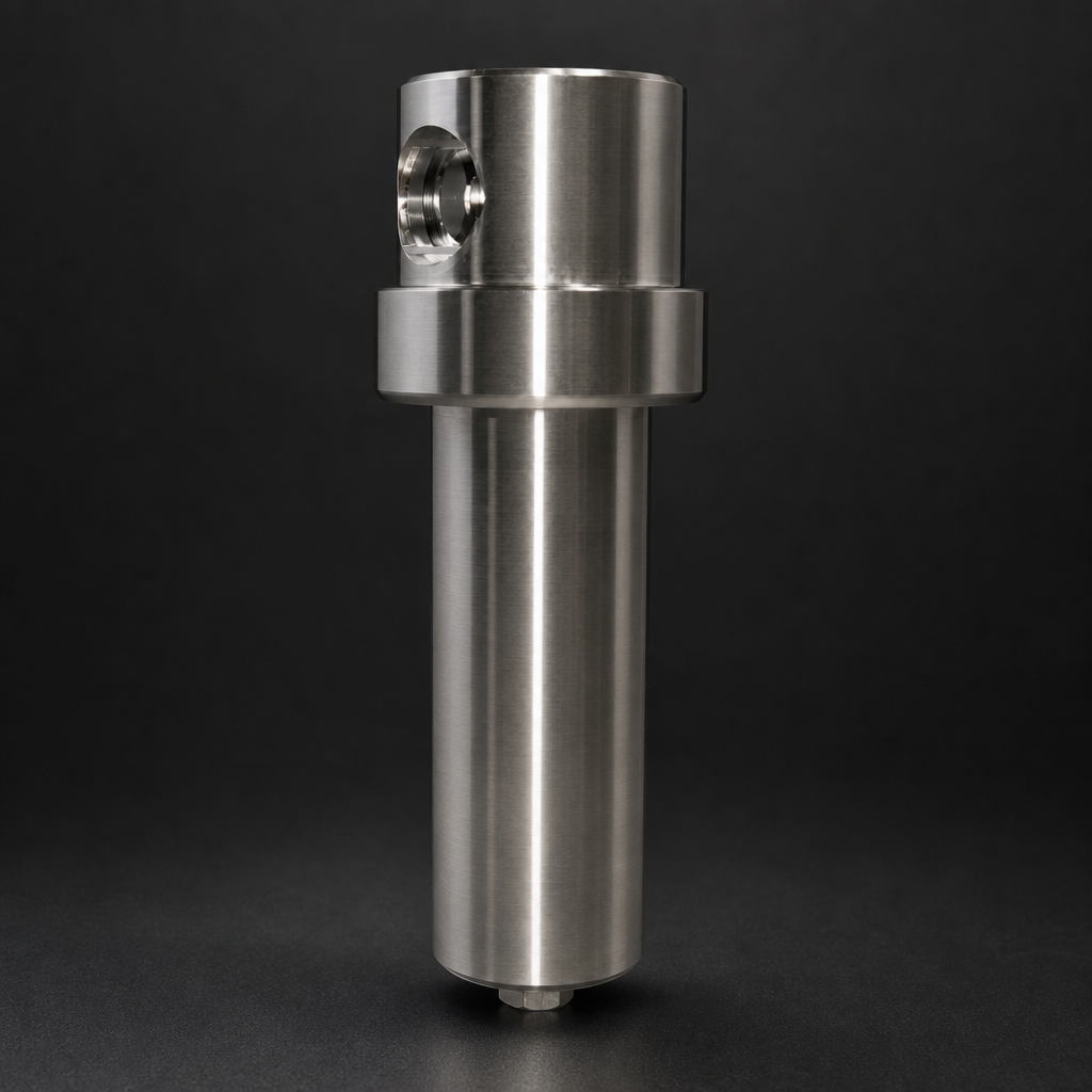
The RF-H-170 high-pressure analyser filter housing is rated to 400 bar and constructed from 316L stainless steel, making it suitable for installation directly on the high-pressure hydrogen supply line downstream of the compressor or storage bank. At this stage, the primary objective is to remove coarse particulate — pipe scale, compressor debris, and weld spatter — before pressure reduction.
The RF-H-170 accepts RF-P particulate filter elements with a 99.99% efficiency rating at ≥ 0.3 µm, providing a robust first line of defence against the particle sizes most likely to cause membrane perforation. The housing's all-stainless construction eliminates the risk of ionic contamination from the filter itself — a critical consideration when the downstream application is a PEM stack.
Stage 2: Point-of-Use Protection with the RF-DIL
The RF-DIL disposable inline filter is designed for installation immediately upstream of the fuel cell stack inlet, after the pressure regulator. At this low-pressure, low-flow duty point, the RF-DIL provides a final particulate barrier that captures any contamination generated within the pressure regulation and distribution pipework downstream of the Stage 1 filter.
The RF-DIL's compact, disposable format means it can be replaced during scheduled maintenance without the need for element extraction tools or housing disassembly — an important practical advantage in fuel cell installations where minimising downtime is a priority. Its borosilicate glass microfibre construction is fully compatible with hydrogen service and introduces no extractable ionic species into the gas stream.
Install the RF-H-170 with the flow direction clearly marked
Technical Comparison: RF-H-170 vs RF-DIL for Fuel Cell Inlet Duty
| Parameter | RF-H-170 (Stage 1) | RF-DIL (Stage 2) |
|---|---|---|
| Maximum pressure | 400 bar | 10 bar (standard) |
| Housing material | 316L stainless steel | 316L stainless steel body |
| Filtration efficiency | 99.99% ≥ 0.3 µm (RF-P element) | 99.99% ≥ 0.3 µm |
| Element type | Replaceable RF-P cartridge | Disposable inline unit |
| Typical installation point | High-pressure supply line, post-compressor | Low-pressure inlet, pre-stack |
| Seal options | FKM/Viton, PTFE | FKM/Viton |
| Hydrogen compatibility | Yes — all-metal wetted parts | Yes — inert wetted materials |
| Maintenance | Element replacement in situ | Full unit replacement |
Selecting the Right Filter Element Grade
For PEM fuel cell applications, R+F FilterElements recommends RF-P particulate elements rather than coalescing grades at the inlet stage. Hydrogen does not carry liquid aerosols under normal operating conditions, and coalescing elements introduce an unnecessary pressure drop penalty. The RF-P element's borosilicate glass microfibre medium provides the required sub-micron particulate retention without the additional depth of a coalescing layer.
Where the hydrogen supply is derived from electrolysis and may carry trace moisture, an RF-C coalescing element upstream of the RF-P stage can be added to the RF-H-170 housing to provide liquid water removal as well. This is particularly relevant for alkaline electrolysis systems, where water carry-over is more common than in PEM electrolysis. For further guidance on electrolysis filtration requirements, see our article on hydrogen electrolysis filtration.
Use our free Engineering Tool to get a filtration recommendation for your specific application in under 2 minutes.
The Cost of Getting It Wrong
Stack replacement is the most significant maintenance cost in a fuel cell system. A single PEM stack for a 100 kW stationary application can cost tens of thousands of euros, and premature failure due to contamination is not covered under most manufacturer warranties. By contrast, a correctly specified two-stage filtration system — RF-H-170 upstream and RF-DIL at the stack inlet — represents a fraction of that cost and can extend stack life by thousands of operating hours.
The economics are straightforward: the cost of filtration consumables over a five-year operating period is typically less than 2% of the cost of a single stack replacement. Filtration is not a cost to be minimised; it is an insurance policy with a very favourable premium.
Installation and Maintenance Considerations
Correct installation is as important as correct product selection. R+F FilterElements recommends the following best practices for fuel cell inlet filtration systems:
- Install the RF-H-170 with the flow direction clearly marked and ensure the drain port is accessible for condensate removal during commissioning.
- Purge the filtration system with dry nitrogen before introducing hydrogen to remove any residual moisture or particulate from the installation process.
- Monitor differential pressure across the RF-H-170 housing using an inline gauge or transmitter. A rising differential pressure indicates element loading and signals the need for element replacement before bypass occurs.
- Replace the RF-DIL at every scheduled maintenance interval, regardless of apparent condition. Its low cost makes condition-based replacement unnecessary, and the risk of a contamination event during the interval between inspections is not worth accepting.
- Use only FKM or PTFE seals in hydrogen service. NBR seals are not recommended due to hydrogen permeation and potential swelling.
For assistance with system sizing and filter selection, R+F FilterElements' online sizing wizard can help identify the correct housing and element combination for your specific flow rate, pressure, and contamination profile. Alternatively, contact the technical team directly via the enquiry page for a bespoke recommendation.
Summary: Protecting Your Fuel Cell Stack Starts at the Inlet
PEM fuel cell membranes are precision components operating at the limits of electrochemical engineering. They are not designed to tolerate particulate contamination above 5 µm or ionic impurities in the parts-per-million range. The hydrogen supply system — with its compressors, pipework, and pressure regulation equipment — is a continuous source of both types of contamination unless active filtration is in place.
A two-stage approach using the RF-H-170 for high-pressure upstream filtration and the RF-DIL for point-of-use protection at the stack inlet provides comprehensive coverage against the contamination mechanisms that cause premature membrane failure. Both products are available from R+F FilterElements and are engineered to European standards for hydrogen service.
Specifying the correct fuel cell inlet filter at the design stage is the single most cost-effective decision you can make to protect stack longevity. Do not leave it as an afterthought.
- Irreversible pinhole formation:
- ISO 14687:2019 defines the hydrogen fuel quality requirements for PEM fuel cell road vehicles, and its limits are instructive for stationary applications as well.
- hydrogen inlet filtration
- For PEM fuel cell applications, R+F FilterElements recommends RF-P particulate elements rather than coalescing grades at the inlet stage.

