Gas turbines are among the most demanding machines in industrial power generation — and among the most sensitive to contamination. Whether installed offshore on a floating production platform or onshore at a combined-cycle power plant, every turbine draws enormous volumes of ambient air through its compressor section. That air carries salt crystals, oil mist, dust, pollen, and fine aerosols. Without a properly engineered gas turbine inlet air filter system, those contaminants attack compressor blades directly, causing fouling, erosion, and measurable efficiency losses that compound over time.
This guide explains the multi-stage filtration approach used in modern turbine inlet systems, the specific challenges of offshore versus onshore environments, and how R+F FilterElements coalescing and particulate filter elements protect compressor hardware and reduce the frequency of costly compressor washing cycles.
Why Compressor Blade Fouling Is a Serious Operational Problem
Compressor blades operate at tight aerodynamic tolerances. Even a thin film of salt, oil, or particulate on the blade surface disrupts the boundary layer, reduces the pressure ratio, and forces the turbine to consume more fuel to maintain output. The efficiency penalty is well-documented: studies across multiple OEM platforms show a 1–3% reduction in thermal efficiency for every 1,000 operating hours without adequate inlet filtration. On a 50 MW gas turbine running at 8,000 hours per year, that translates to hundreds of thousands of euros in additional fuel cost — before accounting for unplanned maintenance.
Salt is particularly aggressive in coastal and offshore environments. Sodium chloride aerosols are hygroscopic — they absorb moisture and form a sticky film that bonds particulate to blade surfaces. In offshore installations, salt fog concentrations can exceed 80 mg/m³ during storm conditions, far above the tolerance limits of unprotected compressor hardware. Lube oil mist from nearby machinery adds a second adhesive layer, creating a composite fouling deposit that resists online water washing.
The Multi-Stage Inlet Filtration Approach
Modern turbine inlet air filtration systems are designed in stages, each targeting a different contaminant class and particle size range. A correctly specified system typically comprises three functional layers:
Stage 1 — Weather Protection and Pre-Separation
Weather hoods, inertial separators, and vane-type demisters remove bulk water droplets, insects, and coarse particulate before the air reaches the filter media. These passive devices handle the high-volume, high-mass fraction of the contaminant load and protect the downstream filter elements from premature saturation. They are especially important in offshore environments where wave spray and rain can introduce liquid water at rates that would overwhelm a filter element within hours.
Stage 2 — Pre-Filtration (Coarse Particulate)
Panel or bag pre-filters with an efficiency rating of F7–F9 (ISO 16890) capture pollen, dust, and coarse aerosols in the 1–10 µm range. These elements are designed for high dust-holding capacity and low initial pressure drop, extending the service life of the final-stage high-efficiency elements. For onshore installations in arid or agricultural environments, this stage is critical — dust loading can reach several grams per cubic metre during seasonal events.
Stage 3 — High-Efficiency Final Filtration (Coalescing + Particulate)
The final stage is where borosilicate glass microfibre coalescing and particulate elements perform the precision work. R+F coalescing filter elements (RF-C series) achieve 99.99% efficiency at ≥ 0.1 µm, capturing sub-micron oil mist and salt aerosols that pass through coarser pre-filters. The borosilicate microfibre matrix provides a high surface area for coalescence — fine droplets merge into larger ones that drain by gravity — while maintaining a low and stable pressure drop across the element life.
Offshore vs. Onshore: Different Challenges, Same Consequence
The contaminant profile at a turbine inlet varies significantly between offshore and onshore installations, and the filtration system must be specified accordingly.
| Parameter | Offshore Platform | Onshore (Arid) | Onshore (Temperate) |
|---|---|---|---|
| Primary contaminant | Salt fog, oil mist | Mineral dust, sand | Pollen, soot, humidity |
| Salt concentration | Up to 80 mg/m³ | < 5 mg/m³ | < 2 mg/m³ |
| Dust loading | Low–moderate | Very high (seasonal) | Moderate |
| Recommended final stage | Coalescing + particulate | High-capacity particulate | Coalescing or particulate |
| Element change interval | 3–6 months | 6–12 months | 12–18 months |
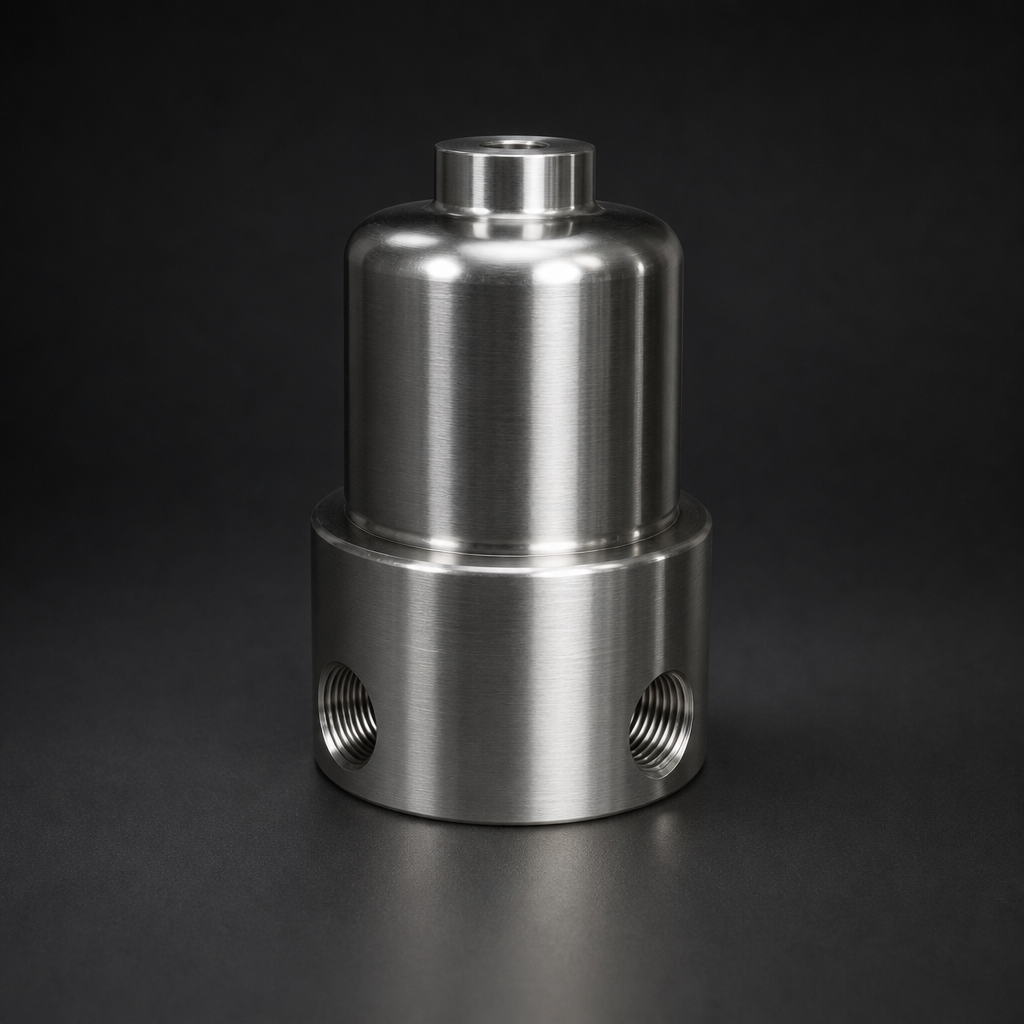
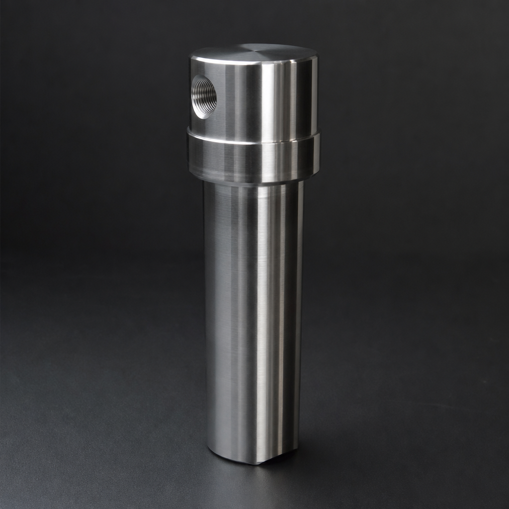
For offshore applications, the coalescing stage is non-negotiable. Salt aerosols in the sub-micron range pass through particulate-only elements and deposit directly on compressor blades. The RF-C coalescing element's borosilicate microfibre matrix is specifically suited to this duty: it captures aerosols by interception and diffusion, coalesces them into drainable droplets, and maintains efficiency even as the element loads with salt. The RF-H-150 process gas housing provides a compact, 316L stainless steel enclosure rated to 100 bar, suitable for pressurised inlet duct installations where space is constrained.
Need help selecting the right filter for your gas turbine inlet?
Use our free Engineering Tool to get a filtration recommendation for your specific application in under 2 minutes.
Key Performance Data for R+F Inlet Filtration Elements
Reducing Compressor Washing Frequency
Compressor washing — both online (water injection at speed) and offline (crank wash) — is the standard corrective measure for blade fouling. Online washing can recover 0.5–1.5% of lost efficiency, but it introduces its own risks: thermal shock to hot-section components, water ingestion events, and the cost of demineralised water and downtime. Offline washing is more effective but requires a full shutdown.
A properly specified inlet filtration system reduces the frequency of both washing types. Operators who upgrade from F7 panel filters to a coalescing + particulate final stage typically report a 40–60% reduction in compressor washing events per year. The capital cost of the filter upgrade is typically recovered within one to two operating seasons through reduced washing costs and fuel savings alone.
For turbine operators managing multiple units, R+F filter elements are available in standard OEM-compatible dimensions, simplifying cross-fleet standardisation. The RF-C and RF-P series cover the most common element sizes used in GE, Siemens, and Solar turbine inlet housings. For applications requiring activated carbon odour or hydrocarbon removal — common near refineries or chemical plants — the RF-AC adsorption element can be added as a fourth stage.
- Compressor blades operate at tight aerodynamic tolerances.
- Modern turbine inlet air filtration systems are designed in stages, each targeting a different contaminant class and particle size range.
- The contaminant profile at a turbine inlet varies significantly between offshore and onshore installations, and the filtration system must be specified accordingly.
- Compressor washing — both online (water injection at speed) and offline (crank wash) — is the standard corrective measure for blade fouling.
Selecting the Right Element for Your Turbine Inlet
Element selection depends on four primary variables: inlet air flow rate (Nm³/h), contaminant type and concentration, available pressure drop budget, and required change interval. R+F FilterElements offers a free engineering sizing consultation for turbine inlet applications. The online engineering sizing tool allows operators to input their turbine's inlet flow, site conditions, and pressure drop limit to receive a recommended element configuration with predicted service life.
For offshore and coastal installations, the standard recommendation is a two-element final stage: RF-C coalescing followed by RF-P particulate, housed in an RF-H-150 or RF-H-160 316L stainless steel housing. For high-dust onshore sites, a single high-capacity RF-P element with an extended dust-holding capacity pre-filter is often more cost-effective. See our guide on coalescing vs. particulate filter elements for a detailed comparison of the two technologies.
Try our Engineering Sizing Tool → or discuss your requirements with our team.