
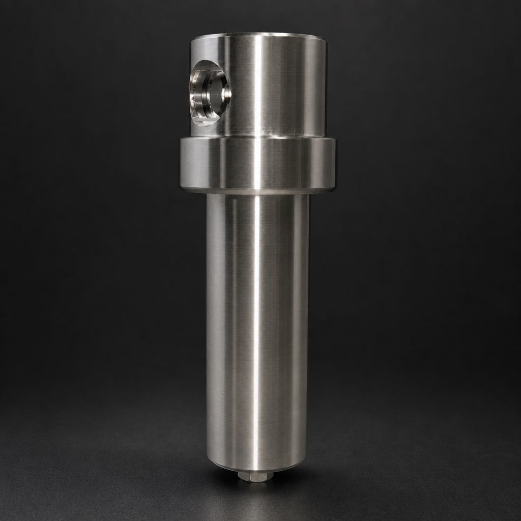
Green ammonia is emerging as one of the most promising hydrogen carriers for the energy transition. Produced from renewable electricity via electrolysis and the Haber–Bosch process, it can be stored and transported at relatively modest pressures — then cracked back into hydrogen at the point of use. The reformer stage, however, introduces a set of filtration challenges that are easy to underestimate. Catalyst dust, residual ammonia, and moisture all threaten downstream equipment, membranes, and fuel cells if they are not removed at the right point in the process train.
This article explains what happens inside an ammonia cracker, why the gas leaving the reformer is far from clean, and how a correctly specified multi-stage filtration system protects your investment and keeps hydrogen purity within specification.
What Happens Inside an Ammonia Cracker?
Ammonia cracking — sometimes called ammonia decomposition or ammonia reforming — is the reverse of the Haber–Bosch synthesis. At temperatures between 650 °C and 900 °C, ammonia (NH₃) is passed over a ruthenium or nickel-based catalyst bed, where it decomposes into hydrogen and nitrogen:
2 NH₃ → 3 H₂ + N₂
Conversion rates above 99.5 % are achievable in well-designed reactors, but the cracked gas leaving the reformer is never perfectly pure. Three categories of contamination are consistently present:
- Catalyst fines and particulate: Mechanical attrition of the catalyst bed releases sub-micron and micron-sized particles into the gas stream. These particles are abrasive and can foul heat exchangers, pressure swing adsorption (PSA) beds, and palladium membrane purifiers.
- Residual ammonia (trace NH₃): Even at high conversion, parts-per-million levels of unconverted NH₃ remain. For proton exchange membrane (PEM) fuel cells, the tolerance is typically below 0.1 ppm; for PSA systems, NH₃ poisons the adsorbent over time.
- Moisture and condensable hydrocarbons: Water is produced during start-up and transient operation. Liquid carryover from upstream storage or vaporisation stages can also introduce aerosols into the cracked gas.
The combination of high temperature at the reactor outlet, rapid cooling in the heat recovery section, and the presence of all three contaminant types means that a single filter stage is never sufficient. A properly engineered filtration train addresses each contaminant class in sequence.
Why Filtration After the Reformer Is Critical
Downstream equipment in a green ammonia-to-hydrogen plant is expensive and sensitive. PSA beds loaded with zeolite or activated alumina adsorbents can be permanently damaged by catalyst dust or liquid water. Palladium membrane modules — used for ultra-high-purity hydrogen production — are irreversibly poisoned by even trace levels of sulphur compounds and can be physically blocked by particulate. PEM fuel cells degrade rapidly when exposed to NH₃ above threshold concentrations.
The economic case for robust filtration is straightforward: the cost of replacing a PSA bed or a membrane module far exceeds the cost of a correctly specified filter system. Unplanned downtime in a hydrogen refuelling station or industrial hydrogen supply chain carries additional penalties that are difficult to quantify but very real.
From a safety perspective, ammonia is toxic (IDLH: 300 ppm) and corrosive. Any filtration system handling cracked ammonia gas must be designed for the full operating pressure and temperature range, with materials compatible with both NH₃ and H₂.
The Three-Stage Filtration Train
R+F FilterElements recommends a three-stage approach for post-reformer filtration in ammonia cracking applications. Each stage targets a specific contaminant class, and the sequence is important — coarser filtration upstream protects finer elements downstream.
Stage 1: High-Temperature Particulate Removal
Immediately downstream of the heat recovery unit, where gas temperatures may still be elevated (100–200 °C), a robust particulate filter removes catalyst fines before they can migrate further into the process train. At this stage, the gas is typically at elevated pressure (10–30 bar, depending on system design), so the housing must be rated accordingly.
The RF-H-152 stainless steel process gas filter housing is well suited to this duty. Constructed from 316L stainless steel with FKM seals rated to 200 °C, it handles the thermal and chemical demands of post-reformer service. Paired with RF-P sintered metal elements (rated to 450 °C), it provides reliable particulate removal at elevated temperatures without the risk of element degradation.
For applications where the gas has already cooled below 100 °C at this stage, standard RF-P particulate elements in borosilicate glass microfibre offer 99.99 % efficiency at ≥ 0.3 µm — sufficient to protect downstream coalescing and adsorption stages from premature loading.
Stage 2: Coalescing — Aerosol and Moisture Removal
Once bulk particulate has been removed, the gas passes through a coalescing filter to capture liquid aerosols — water droplets, condensed ammonia, and any hydrocarbon mist present. Coalescing filtration works by collecting fine aerosol droplets on borosilicate glass microfibre media, allowing them to coalesce into larger droplets that drain to the filter sump under gravity.
R+F FilterElements offers RF-C coalescing elements in a range of sizes to match the volumetric flow of the cracker. These elements achieve 99.99 % efficiency at ≥ 0.1 µm and are available in S-type (200 °C rated) for higher-temperature service. The housing selection depends on flow rate and operating pressure — the RF-H-150 and RF-H-160 process gas housings cover the 100 bar and 250 bar pressure classes respectively, making them appropriate for the majority of distributed ammonia cracking installations.
An automatic drain valve on the coalescing filter sump is strongly recommended. Liquid accumulation in the sump, if not removed, will be re-entrained into the gas stream during flow surges — defeating the purpose of the coalescing stage entirely.
Stage 3: Activated Carbon Adsorption — Trace NH₃ and Odour Removal
The final stage addresses residual ammonia and any trace organic contaminants. Activated carbon adsorption is the standard approach for NH₃ polishing in hydrogen purification trains. R+F FilterElements supplies RF-AC activated carbon adsorption elements and RF-DIA disposable inline adsorbers for this duty.
The RF-DIA inline adsorber is particularly convenient for smaller-scale or distributed cracking units where a full-size adsorption vessel is not justified. It provides activated carbon or molecular sieve media in a compact, replaceable cartridge format — no specialist tools required for element change-out.
For larger installations, the RF-AC element range fits standard R+F housings, allowing the adsorption stage to be integrated into the same filter train as the coalescing stage, minimising pipework and footprint.
Moisture and condensable hydrocarbons:
Material Selection for Ammonia Service
Ammonia is aggressive towards copper, zinc, and their alloys. All wetted components in a post-reformer filtration system must be specified in materials compatible with NH₃. R+F FilterElements' stainless steel housings (316L) are inherently suitable. Seal material selection requires care:
- FKM/Viton seals are the standard choice for ammonia service up to 200 °C — they offer good chemical resistance and are available across the RF-H housing range.
- EPDM seals are suitable for lower-temperature ammonia service and are preferred where oxygen compatibility is also required.
- PTFE seals (rated to 260 °C) are specified for the most demanding high-temperature or high-purity applications.
- NBR seals should be avoided — ammonia causes rapid degradation of nitrile rubber.
Hydrogen embrittlement is a secondary concern at the pressures typical of distributed cracking (below 50 bar), but should be reviewed for high-pressure applications above 200 bar. The RF-H-170 high-pressure analyser filter, rated to 400 bar, is available in configurations reviewed for hydrogen service.
Use our free Engineering Tool to get a filtration recommendation for your specific application in under 2 minutes.
Technical Specification Summary
| Stage | Contaminant Targeted | Recommended R+F Product | Key Rating | Element Type |
|---|---|---|---|---|
| 1 — Particulate | Catalyst fines, solid particles ≥ 0.3 µm | RF-H-152 + RF-P sintered metal | 100 bar, 316L SS, up to 450 °C element | RF-P (sintered metal) or RF-P (glass microfibre) |
| 2 — Coalescing | Water aerosols, liquid NH₃, hydrocarbon mist ≥ 0.1 µm | RF-H-150 / RF-H-160 + RF-C S-type | 100–250 bar, 316L SS, FKM seals | RF-C coalescing (S-type for >100 °C) |
| 3 — Adsorption | Trace NH₃, odour, trace organics | RF-DIA inline adsorber or RF-AC element | Compact inline or housing-mounted | RF-AC activated carbon / molecular sieve |
Sizing Considerations
Correct sizing of each filter stage is essential to avoid excessive pressure drop, premature element loading, or under-filtration. Key parameters to establish before specifying a filtration train for an ammonia cracker include:
- Normal and peak volumetric flow rate (Nm³/h of cracked gas, corrected to operating pressure and temperature)
- Operating pressure at each filter stage (accounting for pressure drop across the reformer and heat recovery section)
- Gas temperature at each filter inlet
- Expected catalyst dust loading (influenced by catalyst type, bed age, and flow velocity through the reactor)
- Acceptable pressure drop across the filtration train (relevant to compressor sizing and overall system efficiency)
R+F FilterElements provides a free online sizing tool that allows engineers to input operating conditions and receive a recommended housing and element combination. For complex or high-pressure applications, the R+F technical team can provide a detailed sizing review — contact R+F FilterElements to discuss your specific requirements.
Integration with Hydrogen Purification
In most green ammonia-to-hydrogen plants, the cracked gas passes through a purification stage — typically PSA or a palladium membrane — before delivery to the end user. The filtration train described above sits between the cracker outlet and the purification inlet. Getting this interface right is critical:
- PSA systems typically require inlet gas free of liquid water and with NH₃ below 1 ppm to protect the adsorbent bed life.
- Palladium membrane purifiers require particulate-free gas (typically < 1 µm) and are sensitive to sulphur compounds and certain organic species.
- PEM fuel cells require hydrogen purity to ISO 14687 Grade D (99.97 % H₂, NH₃ < 0.1 ppm, total hydrocarbons < 2 ppm).
The three-stage filtration train — particulate, coalescing, adsorption — addresses all of these requirements when correctly sized and maintained. Element change-out intervals should be established based on actual operating data; in catalyst-intensive applications, particulate elements may require more frequent replacement than in clean gas service.
For applications where hydrogen purity requirements are particularly stringent, the RF-GMS-170 PTFE hydrophobic membrane separator can be added upstream of the coalescing stage to provide an absolute liquid barrier, preventing any bulk liquid carryover from reaching the coalescing elements during upset conditions.
- Catalyst fines and particulate:
- Downstream equipment in a green ammonia-to-hydrogen plant is expensive and sensitive.
- R+F FilterElements recommends a three-stage approach for post-reformer filtration in ammonia cracking applications.
- Ammonia is aggressive towards copper, zinc, and their alloys.
Conclusion
Green ammonia cracking is a technically mature route to distributed hydrogen production, but the gas leaving the reformer stage is not ready for direct use. Catalyst dust, residual ammonia, and moisture must all be addressed by a correctly specified multi-stage filtration system before the hydrogen reaches purification equipment or end-use applications.
R+F FilterElements, a German-based filtration specialist, offers a complete range of stainless steel process gas housings, coalescing elements, particulate elements, and activated carbon adsorbers suited to post-reformer service. All products are designed to European engineering standards and are available with the seal materials and pressure ratings required for ammonia and hydrogen service.
To discuss filtration requirements for your ammonia cracking project, use the R+F sizing tool or contact the R+F FilterElements team directly.

