
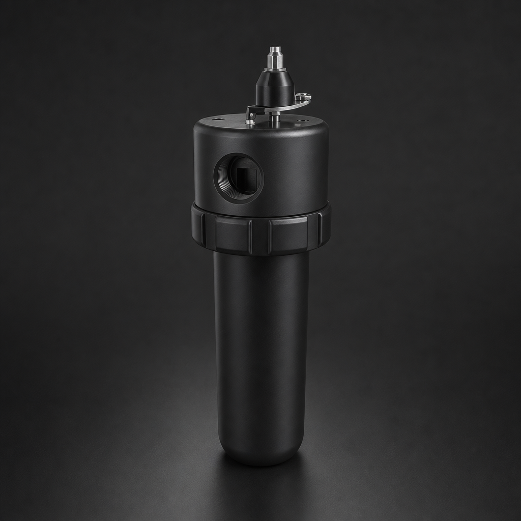
Compressed air is the invisible backbone of modern PCB manufacturing. From component placement and reflow soldering to board cleaning and in-circuit testing, virtually every automated process on the assembly line depends on a reliable supply of clean, dry air. Yet contaminated compressed air remains one of the most overlooked causes of solder defects, board failures, and costly rework — costing electronics manufacturers millions in scrapped product and warranty claims each year.
This guide explains the contamination risks specific to PCB manufacturing, the air quality classes required at each process stage, and how to select the right filtration equipment to protect your production line.
Why Compressed Air Quality Matters in PCB Manufacturing
Modern PCB assembly lines operate at extraordinary precision. Pick-and-place machines position components with tolerances measured in microns; reflow ovens maintain temperature profiles within ±2 °C; automated optical inspection (AOI) systems detect defects at sub-millimetre resolution. Any contamination introduced via compressed air can disrupt these processes in ways that are difficult to trace back to their source.
The three primary contaminants of concern are:
- Oil aerosols and vapour — from compressor lubrication, these coat component leads and PCB pads, preventing proper solder wetting and causing dewetting or non-wetting defects.
- Particulate matter — dust, rust, and pipe scale can block nozzles on pick-and-place heads, contaminate solder paste, and scratch sensitive component surfaces.
- Moisture — water vapour condenses on cold boards and components, causing flux activation failures, corrosion of exposed copper, and short circuits during testing.
For a detailed breakdown of how these contaminants interact with soldering chemistry, see our guide on coalescing vs particulate filter elements and the role each plays in removing specific contamination types.
Air Quality Requirements by Process Stage
Not every compressed air application in a PCB factory demands the same purity level. Understanding the requirements at each stage allows you to design a cost-effective filtration system that applies the right level of treatment where it is genuinely needed.
Component Placement (Pick-and-Place)
Pick-and-place machines use vacuum and blow-off air to handle components. Particulate contamination in blow-off air can deposit on component leads or PCB pads, interfering with solder paste adhesion. ISO 8573-1 Class 2 for particles (≤ 1 µm) and Class 2 for oil (≤ 0.1 mg/m³) is the minimum recommended standard. Point-of-use inline filters such as the RF-DIL series are ideal for protecting individual machine heads.
Reflow and Wave Soldering
Soldering processes are the most sensitive to oil contamination. Even at concentrations below 0.1 mg/m³, oil vapour can inhibit flux activation and cause solder balling or bridging. ISO 8573-1 Class 1 for oil is mandatory. A two-stage filtration train — coalescing followed by activated carbon adsorption — is the industry-standard approach. The R+F compressed air filter range provides both stages in a compact, modular format.
PCB Cleaning and Defluxing
Compressed air used for board cleaning after soldering must be free of both particulates and moisture. Water droplets in the air stream can redeposit flux residues or cause localised corrosion on exposed copper traces. ISO 8573-1 Class 1 for moisture (pressure dew point ≤ −70 °C) is recommended for this application.
In-Circuit and Functional Testing
Test fixtures use pneumatic actuators to press test probes onto board pads. Contaminated air can cause probe sticking, false contact failures, and premature wear of test fixtures. ISO 8573-1 Class 2 for particles and Class 2 for oil is typically sufficient for this application.
Selecting the Right Filtration Equipment
A well-designed filtration system for PCB manufacturing typically consists of three stages, applied in sequence after the compressed air dryer:
| Stage | Filter Type | R+F Product | Removes | ISO 8573-1 Class Achieved |
|---|---|---|---|---|
| 1 — Pre-filter | Particulate (RF-P) | RF-H-310 + RF-P element | Bulk particles ≥ 1 µm, bulk liquid water | Class 2 particles |
| 2 — Coalescing | Coalescing (RF-C) | RF-H-340 + RF-C element | Oil aerosols ≥ 0.1 µm, fine particles | Class 1 oil, Class 1 particles |
| 3 — Adsorption | Activated carbon (RF-AC) | RF-H-340 + RF-AC element | Oil vapour, odour, residual hydrocarbons | Class 1 oil vapour (< 0.003 mg/m³) |
For point-of-use protection at individual machines, the RF-DIL disposable inline filter provides a cost-effective final barrier against particulate contamination introduced downstream of the main filtration system — for example, from ageing pipework or flexible hoses.
Need help selecting the right filter for your PCB manufacturing line?
Use our free Engineering Tool to get a filtration recommendation for your specific application in under 2 minutes.
Semiconductor and High-Purity PCB Applications
For advanced PCB manufacturing — including high-density interconnect (HDI) boards, flexible circuits, and semiconductor packaging — even tighter air quality standards may apply. In these environments, the R+F instrumentation filter range (RF-H-110 to RF-H-170 series) offers 316L stainless steel construction with SilcoNert-coated internals for ultra-pure applications where metallic contamination from aluminium housings is unacceptable.
The RF-H-150 process gas housing, rated to 100 bar in 316L stainless steel, is also used in semiconductor fabs for specialty gas filtration — including nitrogen purge systems used to prevent oxidation during reflow soldering in inert atmosphere ovens. For more on high-purity gas filtration, see our article on ISO 8573-1 compressed air quality classes.
Maintenance and Monitoring Best Practices
Even the best filtration system will fail if maintenance is neglected. For PCB manufacturing environments, we recommend:
- Differential pressure monitoring — fit differential pressure gauges or electronic transmitters across each filter stage. A rising ΔP indicates element loading; replace elements before the pressure drop causes flow starvation to downstream equipment.
- Scheduled element replacement — regardless of ΔP readings, replace coalescing and carbon elements on a fixed schedule (typically every 6–12 months, depending on duty cycle and contamination load).
- Dew point monitoring — install a dew point transmitter downstream of the dryer and upstream of the filtration train. A rising dew point indicates dryer degradation before it causes visible moisture problems on the line.
- Oil vapour spot checks — use oil vapour detector tubes at point-of-use locations quarterly to verify that the carbon adsorption stage is performing correctly.
For guidance on sizing your filtration system to match your compressed air flow rate and pressure, use the R+F Engineering Sizing Tool, which calculates the correct housing and element combination for your specific application parameters.
- Oil aerosols and vapour
- Not every compressed air application in a PCB factory demands the same purity level.
- A well-designed filtration system for PCB manufacturing typically consists of three stages, applied in sequence after the compressed air dryer:
- For advanced PCB manufacturing — including high-density interconnect (HDI) boards, flexible circuits, and semiconductor packaging — even tighter air quality standards may apply.
Related Reading
- Coalescing vs Particulate Filter Elements — Which Do You Need?
- ISO 8573-1 Compressed Air Quality Classes Explained
- Oxygen Filtration Safety — Avoiding Ignition Risks in High-Purity Systems
Try our Engineering Sizing Tool → or discuss your requirements with our team.

