When a hydrogen project moves from a 10 kW pilot electrolyser to a 100 kW commercial stack, the engineering team faces a challenge that is easy to underestimate: the filtration system cannot simply be copied and pasted. Flow rates multiply by a factor of ten or more, contamination profiles shift, pressure demands evolve, and maintenance logistics become a serious operational concern. Getting the filtration architecture right at each scale is critical — not just for gas purity, but for uptime, cost, and long-term reliability.
How Flow Rates Change as Electrolysers Scale
A 10 kW PEM electrolyser typically produces hydrogen at roughly 0.1–0.2 kg/h, corresponding to a volumetric flow of around 1–2 Nm³/h at standard conditions. At 100 kW, that figure rises to approximately 1.5–2 kg/h, or 15–20 Nm³/h. This tenfold increase is not merely a matter of selecting a larger housing — it fundamentally changes which filter element sizes are appropriate, how many parallel trains are needed, and what pressure drop budget is available across the filtration stage.
Filter Element Sizing: Why 25×64 mm Is Not Enough at Scale
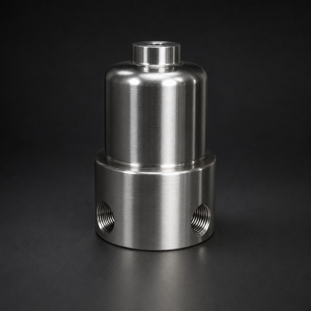
At pilot scale (10 kW), the compact 25×64 mm element format fits neatly into a single process gas housing such as the RF-H-150. This housing is rated to 100 bar and accepts standard coalescing elements (RF-C series) in the 25×64 mm format, making it ideal for lab and demonstration systems where footprint is limited and flow rates are modest.
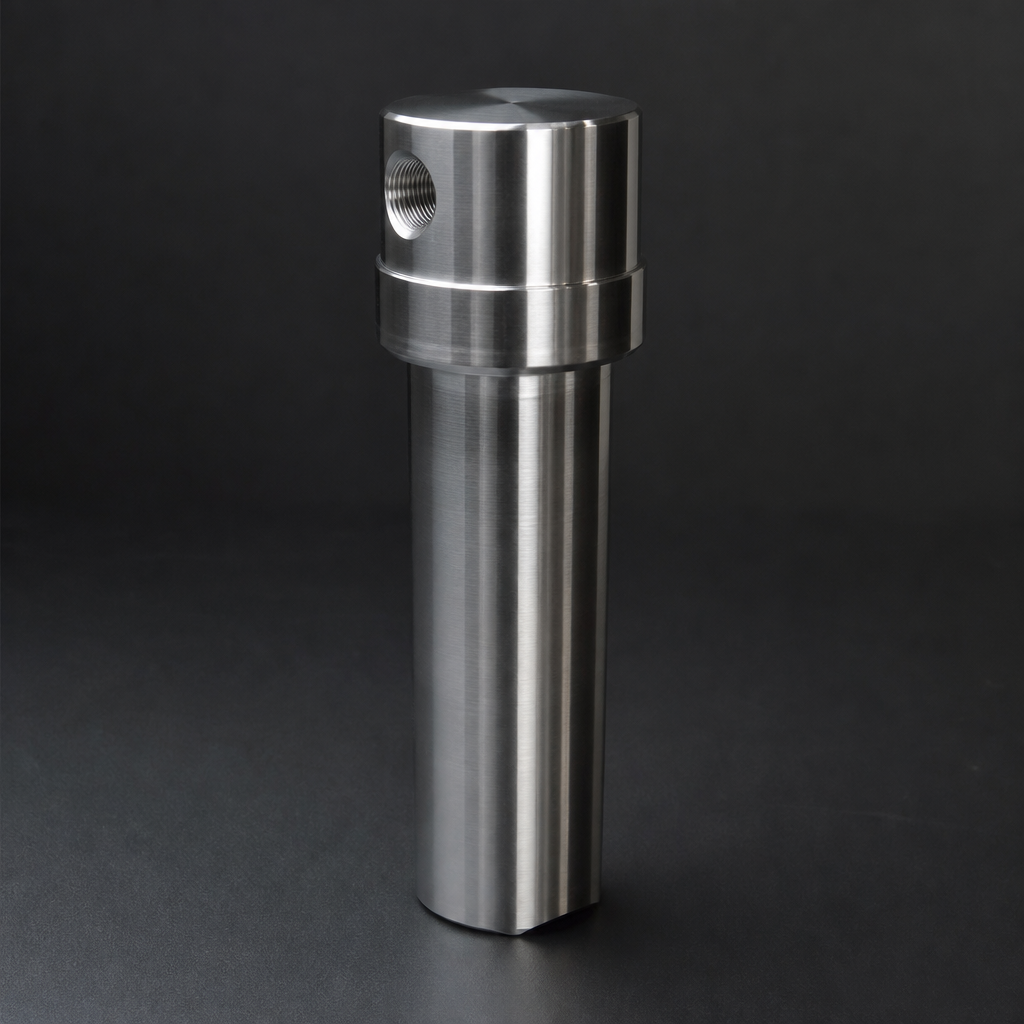
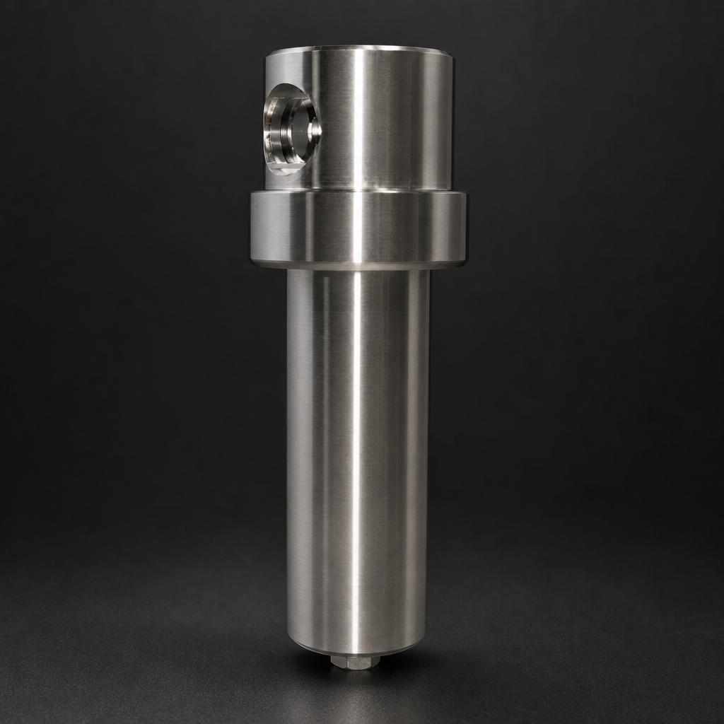
As the electrolyser scales to 50 kW or 100 kW, the 25×64 mm element reaches its practical flow limit. The correct approach is to step up to the 25×178 mm element format, which offers approximately 2.8× the filtration area of the shorter element. For very high flow rates — or where redundancy is required — a parallel train of two or more housings, each fitted with 25×178 mm elements, is the preferred architecture. This approach also simplifies maintenance: one train can be serviced while the other remains online.
The RF-C coalescing elements available from R+F FilterElements achieve 99.99% efficiency at ≥ 0.1 µm, removing electrolyte mist, water droplets, and particulate contamination that would otherwise reach downstream compression or storage equipment. For particulate-only duties, RF-P elements rated at 99.99% efficiency ≥ 0.3 µm are the appropriate choice. Learn more about coalescing vs particulate filter elements and when to use each.
Pressure Considerations Across the Scale-Up Range
PEM electrolysers typically deliver hydrogen at pressures between 7 and 30 bar, though some advanced stacks operate at 50 bar or higher. Alkaline electrolysers generally operate at lower pressures (1–30 bar). As systems scale up, the operating pressure often increases to reduce downstream compression costs — which means the filtration housing must be specified accordingly.
The RF-H-150 (100 bar rated) covers the majority of PEM applications at both pilot and commercial scale. For higher-pressure systems or where additional safety margin is required, the RF-H-160 (250 bar) or RF-H-170 (400 bar) housings are available from R+F FilterElements. All are manufactured in 316L stainless steel and are compatible with hydrogen service. See the full instrumentation and high-pressure filter range for detailed specifications.
Differential pressure monitoring:
How Contamination Profiles Change at Scale
At pilot scale, contamination loads are relatively low and predictable. The primary contaminants from a PEM electrolyser are liquid water (carried over from the membrane), dissolved electrolyte traces, and fine particulate from membrane degradation. A single coalescing stage is typically sufficient.
At commercial scale (100 kW and above), several factors shift the contamination picture:
- Higher absolute liquid carryover: Even if the carryover rate per unit of gas is constant, the absolute volume of liquid reaching the filter is ten times greater. Element loading increases proportionally, and change intervals must be planned accordingly.
- Stack degradation products: Larger stacks with more membrane area generate more particulate from membrane and catalyst layer degradation over time. A dedicated particulate pre-filter (RF-P element) upstream of the coalescing stage can extend coalescing element life significantly.
- Compressor oil ingress: At commercial scale, downstream compression is almost always required. If oil-lubricated compressors are used, an activated carbon adsorption stage (RF-AC element or RF-DIA inline adsorber) must be included downstream of the coalescing filter to meet ISO 8573-1 Class 1 oil content requirements.
For a detailed overview of hydrogen electrolysis filtration requirements, see our guide on hydrogen electrolysis filtration.
Use our free Engineering Tool to get a filtration recommendation for your specific application in under 2 minutes.
Parallel Filtration Trains: When and Why
A single filtration train is acceptable for pilot and small commercial systems where planned downtime for element changes is tolerable. At 100 kW and above — particularly in continuous production or grid-balancing applications — unplanned downtime is costly. The standard engineering response is to install two parallel trains, each sized for 100% of the design flow, with isolation valves on each train.
This "1+1" architecture allows one train to be taken offline for element replacement while the other continues to operate. It also provides redundancy in the event of an unexpected element failure. For very large systems (500 kW and above), a "2+1" arrangement (two duty trains, one standby) is common.
| Electrolyser Scale | H₂ Flow | Recommended Element | Housing | Train Architecture |
|---|---|---|---|---|
| 10 kW (pilot) | ~1–2 Nm³/h | RF-C 25×64 mm | RF-H-150 | Single train |
| 50 kW | ~8–10 Nm³/h | RF-C 25×178 mm | RF-H-150 / RF-H-160 | Single or 1+1 |
| 100 kW | ~15–20 Nm³/h | RF-C 25×178 mm or 51×230 mm | RF-H-150 / RF-H-160 | 1+1 parallel |
| 500 kW+ | 75–100+ Nm³/h | RF-C 51×476 mm multi-element | RF-H-160 / RF-H-170 | 2+1 parallel |
Maintenance Interval Planning at Commercial Scale
At pilot scale, element changes are infrequent and often performed by the engineering team as part of routine system checks. At commercial scale, maintenance becomes a planned operational activity with real cost implications. The key variables are:
- Differential pressure monitoring: Install a differential pressure gauge or transmitter across each filter housing. A rise of more than 0.3–0.5 bar above the clean element ΔP is the standard trigger for element replacement.
- Time-based intervals: Even if ΔP has not reached the trigger threshold, elements should be replaced at least annually in continuous-duty hydrogen service. Electrolyte traces and fine particulate can blind elements gradually without a sharp ΔP rise.
- Standardised element families: Using a consistent element format (e.g., 25×178 mm RF-C across all housings in a plant) reduces spare parts inventory and simplifies procurement. R+F FilterElements offers standardised housing families that accept the same element across multiple housing sizes.
For guidance on filter element selection and sizing, use the R+F Engineering Sizing Tool or explore the full filter elements range.
Cost Optimisation Through Standardised Housing Families
One of the most effective ways to control filtration costs as a hydrogen project scales is to standardise on a single housing family from the outset. The RF-H-150 series, for example, is available in multiple body lengths and element configurations, all accepting the same RF-C and RF-P element formats. This means that as the project grows from pilot to commercial scale, the element specification remains constant — only the number of housings or the element length changes.
Standardisation also simplifies operator training, reduces the risk of incorrect element installation, and allows bulk purchasing of elements at lower unit cost. For projects planning a phased scale-up, it is worth discussing a long-term supply agreement with R+F FilterElements at the outset to lock in pricing and ensure element availability at each phase. Contact our team via the enquiry page to discuss your project requirements.
- A 10 kW PEM electrolyser typically produces hydrogen at roughly 0.
- At pilot scale (10 kW), the compact 25×64 mm element format fits neatly into a single process gas housing such as the RF-H-150.
- PEM electrolysers typically deliver hydrogen at pressures between 7 and 30 bar, though some advanced stacks operate at 50 bar or higher.
- Higher absolute liquid carryover:
Related Reading
- Hydrogen Electrolysis Filtration — A Complete Guide
- Coalescing vs Particulate Filter Elements: Which Do You Need?
- ISO 8573-1 Compressed Air Quality Classes Explained
Try our Engineering Sizing Tool → or discuss your requirements with our team.