
Compressed air systems are often treated as a single filtration challenge — fit a coalescer, remove the oil mist, and move on. But this approach leaves a critical contamination pathway wide open: oil vapour and dissolved hydrocarbons that pass straight through even the finest coalescing media. For applications demanding ISO 8573-1 Class 1 oil content, a single-stage coalescer is simply not enough.
What a Coalescer Actually Does — and What It Cannot Do
A coalescing filter element works by capturing liquid aerosols and fine oil mist suspended in the compressed air stream. The borosilicate glass microfibre matrix of an RF-C coalescing element achieves 99.99% efficiency at particles ≥ 0.1 µm, draining collected liquid downward into a sump for automatic or manual discharge.
The physics of coalescence, however, only apply to liquid-phase contamination. Oil vapour — the gaseous, molecular form of hydrocarbon contamination — behaves like a gas. It passes through the fibre matrix without being captured, because there is no liquid droplet to intercept. At typical compressed air temperatures of 20–40 °C, a significant fraction of total oil contamination exists in vapour form, particularly when the upstream compressor runs hot or uses synthetic lubricants with high vapour pressure.
The Two-Stage Solution: RF-C Coalescer + RF-AC Adsorber
The correct engineering approach pairs two complementary technologies in series. The RF-C coalescing stage handles all liquid-phase contamination — bulk liquid, aerosols, and fine mist — while the RF-AC activated carbon adsorption stage captures the remaining vapour-phase hydrocarbons through molecular adsorption onto a granular activated carbon bed.
This two-stage architecture is not merely a best practice — it is the only technically valid route to ISO 8573-1 Class 1 oil content in a compressed air system. R+F FilterElements offers both stages as a matched system, sized for the same flow rate and pressure rating.
Understanding the RF-AC Adsorber: Granular Media vs. Single-Cartridge Competitors
The RF-AC adsorption element uses a bed of granular activated carbon — the same principle used in industrial solvent recovery and air purification. Activated carbon has an enormous internal surface area (typically 800–1,200 m²/g), providing vast adsorption capacity for hydrocarbon vapours. As compressed air passes through the bed, oil vapour molecules are captured by van der Waals forces onto the carbon surface.
A key advantage of the granular bed design is replaceability without housing replacement. When the carbon bed is exhausted — indicated by a breakthrough of oil vapour downstream — the RF-AC element is simply swapped out. The housing, pipework, and instrumentation remain in place. This contrasts with some competitor single-cartridge activated carbon solutions, where the entire filter assembly must be replaced, generating more waste and higher lifecycle cost.
Laser cutting and precision machining
Two-Stage vs. Single-Stage: A Direct Comparison
| Parameter | Coalescer Only | RF-C + RF-AC Two-Stage |
|---|---|---|
| Liquid aerosol removal | ✓ 99.99% ≥ 0.1 µm | ✓ 99.99% ≥ 0.1 µm |
| Oil vapour removal | ✗ Not possible | ✓ < 0.003 mg/m³ residual |
| ISO 8573-1 Class 1 oil | ✗ Not achievable | ✓ Achievable |
| Dissolved hydrocarbons | ✗ Pass through | ✓ Adsorbed onto carbon bed |
| Element replacement | Element only | Element only (housing retained) |
| Suitable for food/pharma | ✗ Insufficient | ✓ With correct element grades |
Use our free Engineering Tool to get a filtration recommendation for your specific application in under 2 minutes.
Selecting the Right Housing and Element Sizes
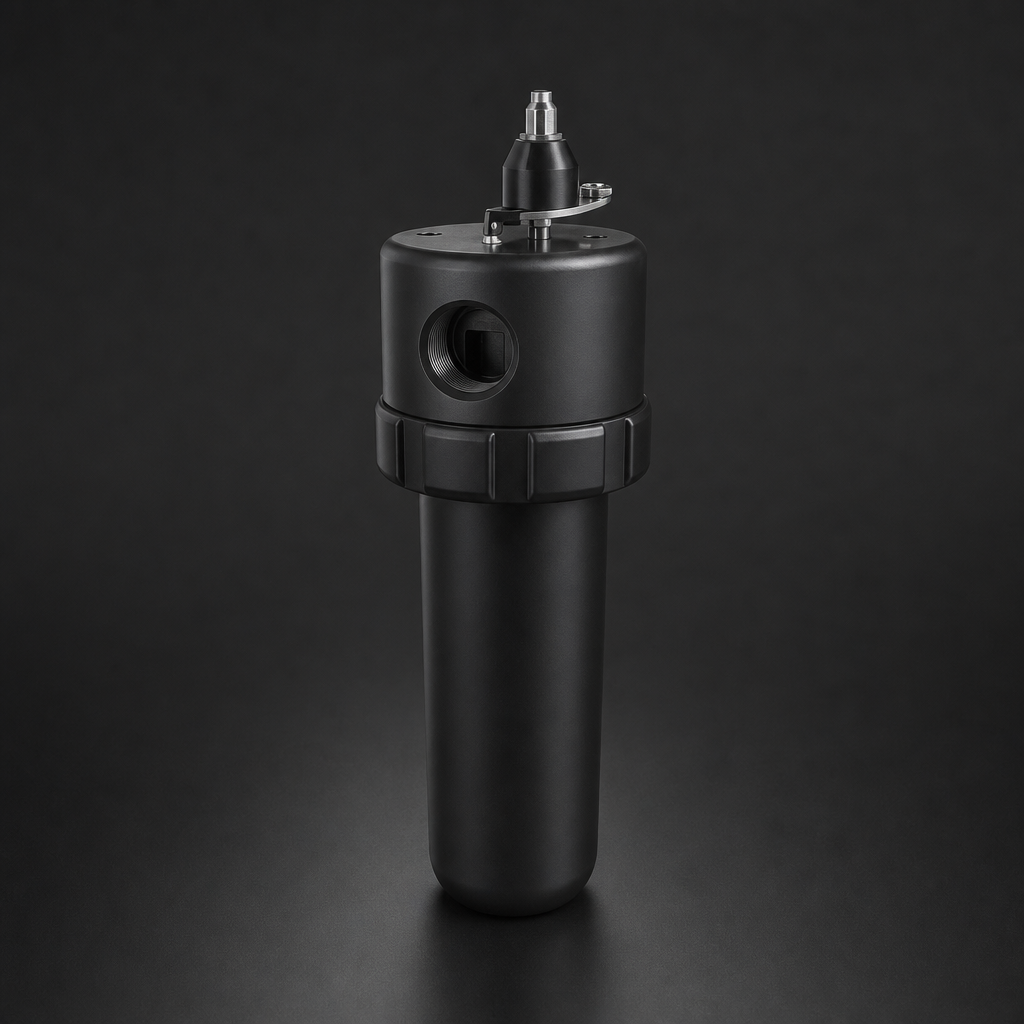
Both the RF-C coalescer and RF-AC adsorber are available in the RF-H-310 to RF-H-395 compressed air filter housing range, covering flow rates from a few Nm³/h up to 12,000 Nm³/h at 17 bar. The two housings should be matched in size — the same housing body accepts both element types, simplifying spare parts management.
For the coalescing stage, element selection follows the required ISO 8573-1 class for particulate and aerosol. For most industrial applications, the RF-C element in the appropriate size (12032, 12057, 25064, 25178, 51230, or 51476) delivers Class 1 aerosol performance. The RF-AC adsorber element is then selected to match the same housing size, ensuring consistent pressure drop and flow characteristics across both stages.
Where space is constrained, R+F FilterElements also offers RF-DIL point-of-use inline filters and RF-DIA inline adsorbers for localised treatment at individual machine connections, without requiring a full housing installation.
Pressure Drop Considerations for Two-Stage Systems
Adding a second filter stage inevitably increases system pressure drop. For a correctly sized two-stage system, the combined pressure drop across a clean RF-C + RF-AC pair is typically 0.15–0.35 bar at rated flow. This is well within the acceptable range for most compressed air networks, and the energy cost of this additional drop is far outweighed by the cost of product contamination, compressor damage, or regulatory non-compliance in sensitive applications.
Pressure drop rises as elements load with contamination. Differential pressure gauges or transmitters fitted to each housing allow maintenance teams to track element condition and schedule replacement before breakthrough occurs. For the RF-AC adsorber, oil vapour breakthrough is the primary indicator — a downstream oil vapour monitor provides the most reliable signal for carbon bed exhaustion.
Applications Where Two-Stage Treatment Is Non-Negotiable
Certain industries and processes cannot tolerate any oil contamination in their compressed air supply. Two-stage RF-C + RF-AC treatment is the standard approach for:
- Food and beverage processing — direct product contact air, packaging, and conveying
- Pharmaceutical manufacturing — cleanroom environments, tablet coating, lyophilisation
- Electronics assembly — component handling, wave soldering, conformal coating
- Breathing air systems — where oil vapour poses a direct health risk
- Laser cutting and precision machining — where oil contamination damages optics or workpieces
- Analytical instrumentation — where hydrocarbon background affects measurement accuracy
For process gas applications at higher pressures, the same two-stage principle applies using RF-H-150 or RF-H-160 process gas housings, which are rated to 100 bar and 250 bar respectively. See also our guide to coalescing vs. particulate filter elements for a deeper look at element selection principles.
- A coalescing filter element works by capturing liquid aerosols and fine oil mist suspended in the compressed air stream.
- The correct engineering approach pairs two complementary technologies in series.
- replaceability without housing replacement
- Both the RF-C coalescer and RF-AC adsorber are available in the RF-H-310 to RF-H-395 compressed air filter housing range, covering flow rates from a few Nm³/h up to 12,000 Nm³/h at 17 bar.
Related Reading
- ISO 8573-1 Compressed Air Quality Classes Explained
- Coalescing vs. Particulate Filter Elements: Which Do You Need?
- Filtration Requirements for Hydrogen Electrolysis Systems
Try our Engineering Sizing Tool → or discuss your requirements with our team.

