
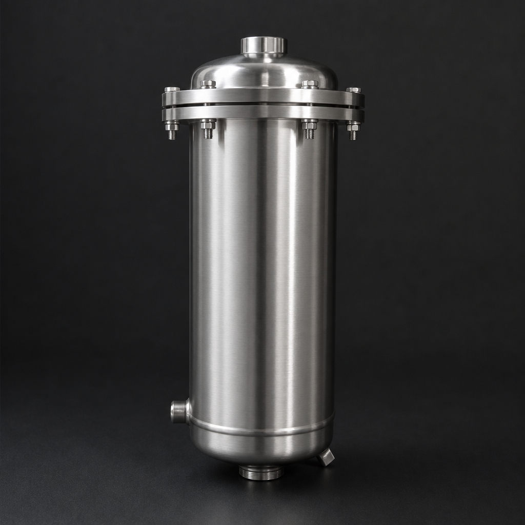
Der Ölnebel, den Sie nicht sehen, ist der, der Sie Geld kostet
Jede ölgedichtete Drehschieber-Vakuumpumpe gibt ein Gemisch aus Luft und Ölaerosol ab. Unter normalen Betriebsbedingungen enthält dieser Nebel submikrone Öltröpfchen — typischerweise zwischen 0,1 und 1,0 µm — die für das bloße Auge praktisch unsichtbar sind. Möglicherweise bemerken Sie einen leichten Schleier am Abgasanschluss oder einen dünnen Film auf nahegelegenen Oberflächen. Doch wenn das Problem sichtbar wird, läuft der Schaden bereits seit Monaten.
Ungefiltert verursacht Vakuumpumpen-Ölnebel eine Reihe von Problemen: kontaminierte Arbeitsbereiche, beschleunigter Geräteverschleiß, verschwendetes Schmieröl und mögliche Überschreitung von Arbeitsplatz-Expositionsgrenzwerten.
Was genau tritt aus dem Vakuumpumpen-Abgas aus?
Ölgedichtete Vakuumpumpen — Drehschieber-, Drehkolben- und Flüssigkeitsring-Typen — verwenden Öl sowohl als Dichtmittel als auch als Kühlmittel. Während des Verdichtungszyklus werden Gas und Öl intensiv vermischt. Der interne Abscheider der Pumpe entfernt den Großteil des Öls, jedoch wird stets ein Restanteil als feines Aerosol mit dem Abgas ausgetragen.
Der Abgasstrom enthält typischerweise:
- Ölaerosol: Submikrone Tröpfchen (0,1–1,0 µm), typischerweise 5–50 mg/m³ je nach Pumpentyp, Alter und Betriebstemperatur
- Öldampf: Gasförmiges Öl, dessen Anteil mit der Abgastemperatur steigt — besonders relevant oberhalb von 80 °C
- Prozessverunreinigungen: Was auch immer die Pumpe evakuiert hat — Lösemittel, Feuchtigkeit, Partikel, chemische Dämpfe
Die versteckten Kosten
Bei einer mittelgroßen Drehschieberpumpe mit 100 m³/h entspricht selbst ein moderater Ölübertrag von 20 mg/m³ einem Verlust von rund 0,5 Litern Öl pro 24-Stunden-Tag. Dieses Öl landet auf Ihren Wänden, Ihren Geräten und in der Luft, die Ihre Mitarbeiter einatmen.
Die tatsächlichen Kosten ungefilterten Abgases
Die Kosten werden selten in einer einzigen Budgetposition erfasst — sie verteilen sich auf Wartung, Verbrauchsmaterialien, Compliance und Produktivitätsverluste.
| Kostenkategorie | Mechanismus | Typische Auswirkung |
|---|---|---|
| Ölverbrauch | Übertragsverlust durch Abgas | 0,3–1,5 Liter/Tag pro Pumpe |
| Wartungsaufwand | Reinigung von Ölrückständen auf Oberflächen und in Leitungen | 2–8 Stunden/Monat pro Anlage |
| Nachgelagerte Anlagen | Ölverschmutzung von Leitungen, Wäschern, Wärmetauschern | Verringerte Effizienz, beschleunigte Korrosion |
| Arbeitsschutz-Compliance | Ölnebel überschreitet AGW (typischerweise 5 mg/m³) | Behördliche Maßnahmen, mögliche Bußgelder |
| Produktkontamination | Luftgetragenes Öl gelangt über RLT-Anlagen in Reinbereiche | Chargenrückweisung, Qualitätsabweichungen |
| Umwelt | Ölaerosol-Emission in die Atmosphäre | Genehmigungsverstöße, Sanierungskosten |
Funktionsweise von Koaleszenz-Abgasfiltern
Ein Vakuumpumpen-Abgasfilter ist im Wesentlichen ein Koaleszenzabscheider, der direkt am Abgasanschluss der Pumpe montiert wird. Das Wirkprinzip: Submikrone Öltröpfchen treten in das Filterelement ein, prallen auf Borsilikat-Glasmikrofasern und verschmelzen schrittweise zu größeren Tropfen, die durch Schwerkraft abfließen.
Abgas tritt in den Elementkern ein
Ölbeladenes Abgas strömt von innen nach außen durch das Koaleszenzmedium des Elements.
Mikrofasern scheiden Tröpfchen ab
Borsilikat-Glasmikrofasern fangen submikrone Öltröpfchen im progressiv dichteren Medium ab.
Tröpfchen koaleszieren und wachsen
Kleine Tröpfchen verschmelzen zu größeren, schwereren Tropfen. Ein Rückeintragungsschutzgewebe verhindert, dass sie erneut in den Gasstrom gelangen.
Reines Abgas tritt aus, Öl fließt ab
Gereinigtes Gas verlässt das Gehäuse. Koalesziertes Öl fließt in einen Sammelbehälter und kann der Pumpe zurückgeführt werden.
Wesentliche Unterschiede zu Inline-Koaleszenzfiltern
Die Durchströmungsrichtung ist von innen nach außen (entgegengesetzt zu den meisten Inline-Koaleszenzfiltern). Der Betriebsdruck liegt nahe Atmosphärendruck (max. 2 bar), was leichtere Gehäusekonstruktionen ermöglicht. Die Temperatur ist ein relevanter Faktor — Abgastemperaturen von 60–100 °C sind normal.
CS-Koaleszenzelemente: speziell für den Abgaseinsatz entwickelt
Nicht alle Koaleszenzelemente sind für den Einsatz im Vakuumpumpen-Abgas geeignet. Standard-Koaleszenzelemente für Druckluft verwenden ein Fluorkohlenstoff-Bindemittel, das ihren Temperatureinsatzbereich begrenzt.
CS-Koaleszenzelemente sind speziell für diese Anwendung ausgelegt:
- Borsilikat-Glasmikrofaser-Medium mit Silikat-Bindemittel — thermisch stabil bis 200 °C
- Optimiert für hohe Ölbeladung — verarbeitet konzentriertes Aerosol ohne vorzeitiges Verblocken
- Rückeintragungsschutzgewebe: Außenwicklung verhindert, dass koaleszierte Tröpfchen wieder in den Gasstrom eingetragen werden
- Leistung: 99,9 % Abscheidegrad bei 0,1 µm, klassifiziert als RF-CS Güteklasse HE
Aluminium- vs. Edelstahlgehäuse
Abgasfiltergehäuse sind in zwei Werkstoffvarianten erhältlich, die jeweils für unterschiedliche Betriebsbedingungen geeignet sind:
Aluminiumgehäuse (RF-H-420–456 Serie)
Die Standardwahl für die meisten Anwendungen. Leicht und kosteneffizient. Max. 120 °C, 2 bar. Anschlussgrößen ½″ bis 3″ NPT. Durchflussbereich 5–765 m³/h. Nitril-Dichtungen als Standard.
Edelstahlgehäuse (RF-H-420S–456S Serie)
Für korrosive Abgase, Temperaturen über 120 °C oder wenn 316L vorgeschrieben ist. Max. 200 °C, 2 bar. Viton (FKM)-Dichtungen. Erforderlich für die chemische Verfahrenstechnik, pharmazeutische GMP-Produktion und Hochtemperatur-Vakuumtrocknung.
Auslegung: den richtigen Volumenstrom ermitteln
Eine korrekte Auslegung ist entscheidend. Ein zu klein dimensionierter Abgasfilter erzeugt einen übermäßigen Gegendruck, der das Vakuumvermögen reduziert und den Energieverbrauch erhöht. Der Auslegungsparameter ist einfach: Den Nennvolumenstrom des Filters dem Fördervolumen der Pumpe (FAD) anpassen, mit einem Sicherheitszuschlag von 20–30 %.
| Pumpenfördervolumen | Modell (AL) | Modell (SS) | Elemente |
|---|---|---|---|
| Bis 5 m³/h | RF-H-420 | RF-H-420S | 1 |
| Bis 15 m³/h | RF-H-425 | RF-H-425S | 1 |
| Bis 35 m³/h | RF-H-430 | RF-H-430S | 1 |
| Bis 75 m³/h | RF-H-433 | RF-H-433S | 3 |
| Bis 150 m³/h | RF-H-443 | RF-H-443S | 3 |
| Bis 170 m³/h | RF-H-437 | RF-H-437S | 7 |
| Bis 340 m³/h | RF-H-447 | RF-H-447S | 7 |
| Bis 765 m³/h | RF-H-456 | RF-H-456S | 16 |
Temperaturkorrektur
Bei Pumpen mit erhöhten Abgastemperaturen (über 80 °C) ist ein Temperaturkorrekturfaktor anzuwenden: Das Pumpen-FAD mit (TAbgas + 273) / 293 multiplizieren, um den tatsächlichen Volumenstrom am Filter zu erhalten.
Ölrückgewinnung: Verluste in Einsparungen umwandeln
Ein gut ausgelegtes Abgasfiltrationssystem entfernt nicht nur Öl — es gewinnt es zurück. Koalesziertes Öl fließt durch Schwerkraft aus dem Filterelement ab und wird bei korrekter Verrohrung direkt in den Ölbehälter der Pumpe zurückgeführt.
Damit die Ölrückführung korrekt funktioniert:
- Die Filterablaufleitung muss zum Öleinfüllstutzen der Pumpe oder einem Sammelbehälter zurückgeführt werden
- Die Ablaufleitung muss durchgehend nach unten geneigt sein — keine U-Bögen oder Siphons
- Ein Rückschlagventil kann erforderlich sein, um zu verhindern, dass Pumpenöl in den Filter zurückgesaugt wird
- Das gesammelte Öl sollte vor der Wiederverwendung regelmäßig auf Verunreinigungen geprüft werden
Installationshinweise
Senkrecht montieren
Der Filter muss senkrecht mit dem Ablauf nach unten montiert werden, um den Schwerkraftablauf des Öls zu gewährleisten. Keine horizontale Montage.
Abgasleitungen kurz halten
So nah wie möglich am Abgasanschluss der Pumpe installieren. Lange Leitungen führen zur Ölkondensation in der Rohrleitung.
Größere Modelle abstützen
RF-H-433 und größer sind im beladenen Zustand schwer. Unabhängig abstützen — nicht frei auskragend am Abgasanschluss befestigen.
Gegendruck überwachen
Integrierte Manometer verwenden oder ein separates Manometer in die Abgasleitung einbauen. Element bei 0,3 bar ΔP ersetzen.
Wann das Element zu ersetzen ist
Koaleszenzelemente im Abgaseinsatz haben eine begrenzte Standzeit. Das Glasmikrofaser-Medium belädt sich schrittweise mit Verunreinigungen, die nicht abfließen können. Mit zunehmender Beladung des Elements steigt der Druckabfall.
Austauschriterien
Ersetzen wenn: der Druckabfall 0,3 bar (300 mbar) erreicht, oder den vom Pumpenhersteller maximal zulässigen Gegendruck — je nachdem, welcher Wert zuerst erreicht wird. Wenn Ölübertrag stromabwärts sichtbar wird, ist das Element gesättigt. Koaleszenzelemente können nicht gereinigt oder regeneriert werden — sie müssen ersetzt werden.
Branchen und Anwendungen
Die Vakuumpumpen-Abgasfiltration ist in nahezu jeder Branche relevant, die ölgedichtete Vakuumpumpen einsetzt:
- Pharmazeutische Produktion: Vakuumtrocknung, Destillation, Gefriertrocknung — sauberes Abgas gemäß GMP erforderlich. Edelstahlgehäuse typischerweise vorgeschrieben.
- Lebensmittel und Getränke: Vakuumverpackung, Entgasung, Eindampfung — Schutz vor Produktkontamination.
- Chemische Verfahrenstechnik: Reaktorevakuierung, Lösemittelrückgewinnung — korrosive Abgasströme erfordern 316L-Ausführung.
- Halbleiterfertigung: Ultrareine Umgebungen, in denen jegliche luftgetragene Kontamination unzulässig ist.
- Labore und Forschung: Rotationsverdampfer, Vakuumöfen — kompakte Filter (RF-H-420) für kleine Tischpumpen.
- Kunststoff und Verbundwerkstoffe: Vakuumformen, Autoklavieren — hohe Ölbeladung durch Dauerbetriebspumpen.
- Druck und Verpackung: Vakuum-Spanntische, pneumatische Zuführung — Schutz der Raumluftqualität.
Fazit
Vakuumpumpen-Abgasfiltration ist keine optionale Maßnahme — sie ist eine grundlegende ingenieurtechnische Anforderung. Die Kosten für einen Filter und den regelmäßigen Elementwechsel sind ein Bruchteil der Gesamtbetriebskosten einer Vakuumpumpe, eliminieren jedoch Ölverluste, schützen Ihre Anlage und stellen die Einhaltung von Umwelt- und Arbeitsschutzvorschriften sicher.
Abgasfilter in wenigen Minuten auslegen
Geben Sie Ihr Pumpenfördervolumen und die Betriebsbedingungen ein — das Engineering-Tool empfiehlt das passende Gehäusemodell und den geeigneten Elementtyp.

