When plant engineers evaluate compressed air filtration, the purchase price of a filter housing or replacement element is often the first — and sometimes only — figure that enters the calculation. Yet in most industrial facilities, the energy consumed by the compressor to overcome filter pressure drop dwarfs the capital cost of the filter itself within the first year of operation. Understanding the true compressed air filter energy cost is therefore not an accounting exercise; it is a core engineering decision that directly affects your site's electricity bill and carbon footprint.
Why Pressure Drop Is an Energy Tax on Your Compressor
Every filter element, housing, and fitting in a compressed air system introduces resistance to flow. The compressor must work harder to maintain the required downstream pressure, consuming additional electrical energy in the process. This additional load is commonly referred to as the pressure drop energy cost, and it accumulates continuously — 24 hours a day, every day the system runs.
The relationship between pressure drop and energy consumption is well established in compressor engineering. As a practical rule of thumb:
- For every 0.1 bar of additional pressure drop across the filtration train, a typical rotary screw compressor requires approximately 0.6 % more electrical power to maintain the same outlet pressure.
- Equivalently, for every 0.5 bar of pressure drop, energy consumption increases by roughly 3 %.
- A system running at 7 bar(g) with 1.0 bar of total filtration pressure drop is effectively operating at 8 bar(g) at the compressor outlet — a significant and entirely avoidable energy penalty.
These figures assume a well-maintained, modern variable-speed or fixed-speed rotary screw compressor. Older reciprocating compressors may show even steeper penalties. The key insight is that pressure drop is not a fixed, unavoidable cost — it is a variable that can be engineered down through correct filter selection and sizing.
How to Calculate the Annual Energy Cost of Pressure Drop
The following formula allows you to estimate the annual electricity cost attributable to a given pressure drop across your filtration system:
Annual Energy Cost (£) = P_motor (kW) × (ΔP / P_outlet) × Hours_per_year × Electricity_rate (£/kWh)
Where:
- P_motor = installed compressor motor power in kW
- ΔP = total filtration pressure drop in bar
- P_outlet = compressor outlet pressure in bar(a)
- Hours_per_year = annual operating hours (e.g. 8,000 h for two-shift operation)
- Electricity_rate = your site electricity tariff in £/kWh
This formula is a linear approximation that holds well for pressure drops up to approximately 1.5 bar. For higher drops, or for systems with multiple compressors running in parallel, a more detailed thermodynamic analysis is advisable.
Worked Example: 75 kW Compressor, Two-Shift Operation
Consider a typical manufacturing site with a 75 kW rotary screw compressor running at 7 bar(g) (8 bar absolute), operating 8,000 hours per year, with an electricity tariff of £0.18/kWh. The filtration train consists of a coalescing pre-filter and a particulate after-filter, both sized to the minimum housing diameter — a common cost-saving measure at the point of purchase.
| Scenario | Total ΔP (bar) | Additional Power (kW) | Annual Energy Cost | Cost vs. Baseline |
|---|---|---|---|---|
| Correctly sized filters (new elements) | 0.20 | 1.88 | £2,700 | Baseline |
| Undersized housings (new elements) | 0.50 | 4.69 | £6,750 | +£4,050/yr |
| Correctly sized, elements at end-of-life (0.7 bar ΔP) | 0.70 | 6.56 | £9,450 | +£6,750/yr |
| Undersized housings, elements at end-of-life (1.0 bar ΔP) | 1.00 | 9.38 | £13,500 | +£10,800/yr |
The numbers are striking. A site that chose undersized filter housings to save perhaps £300–£500 on capital expenditure may be paying over £4,000 per year in additional electricity — every year, for the life of the installation. And if element change intervals are extended beyond the recommended schedule, the penalty compounds further.
The Hidden Cost of Undersized Filter Housings
Filter housings are rated by their nominal flow capacity, but the actual pressure drop at a given flow rate depends on the housing bore, the element face velocity, and the element's own differential pressure characteristic. When a housing is selected at or near its maximum rated flow, the element operates at high face velocity, generating elevated pressure drop even when new.
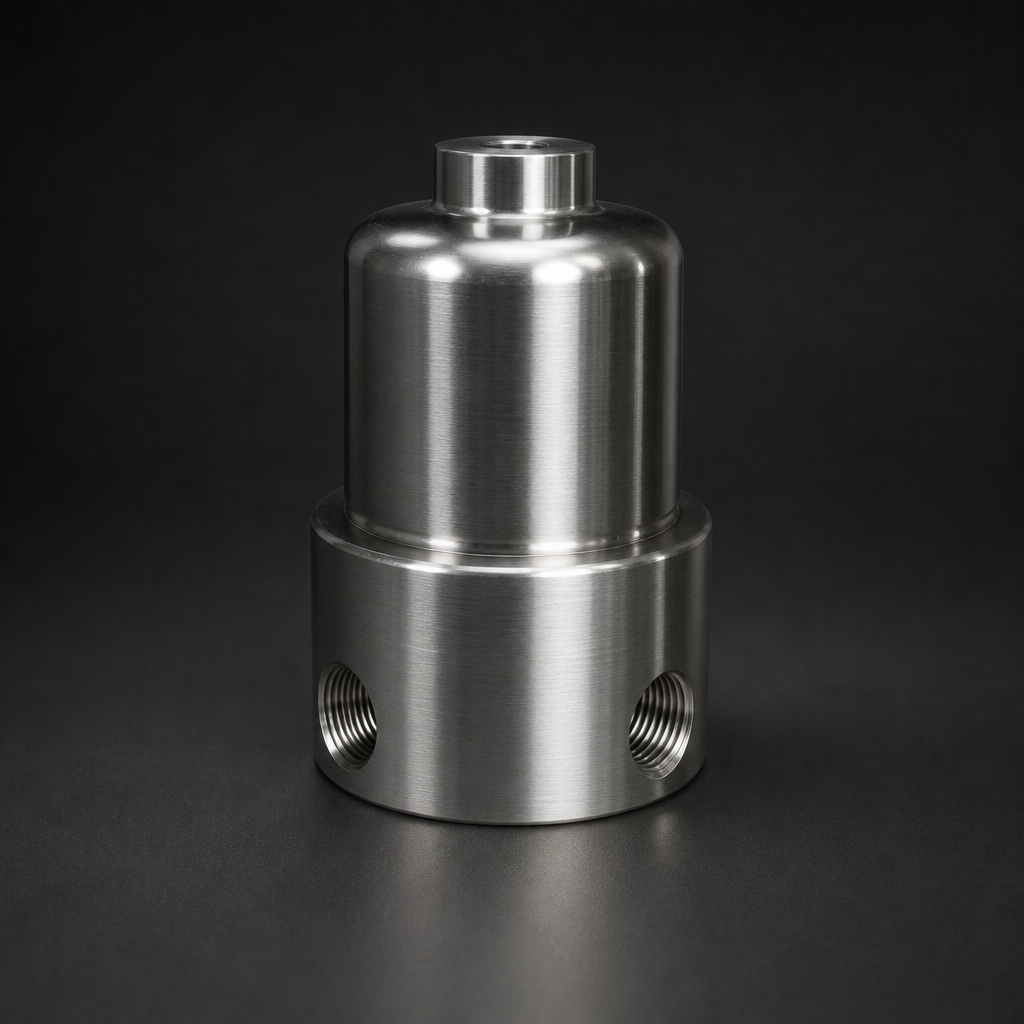
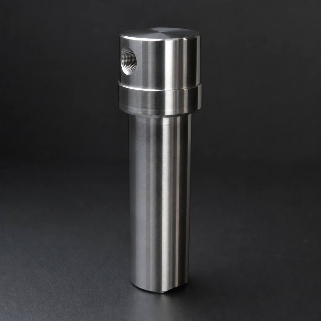
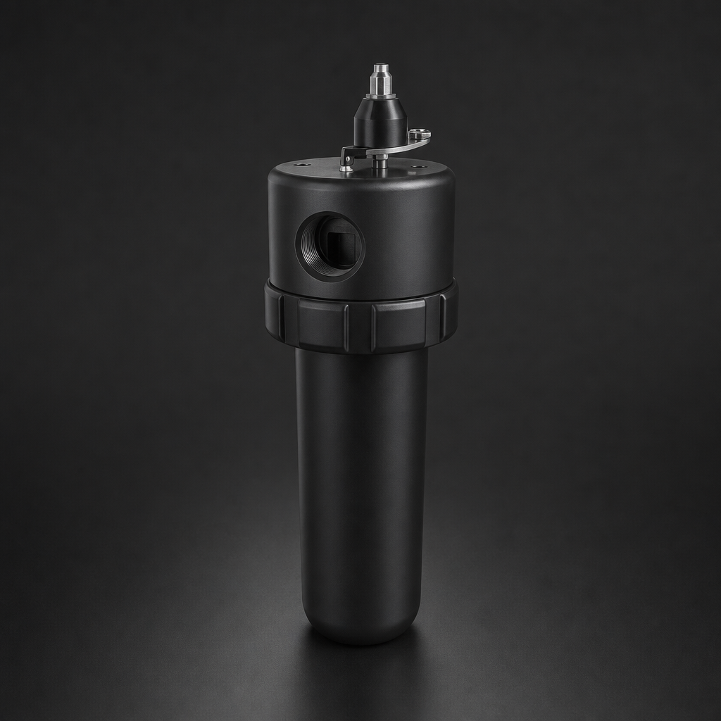
R+F FilterElements offers its own range of compressed air filter housings — the RF-H-310 to RF-H-395 series — specifically engineered to provide low initial pressure drop across a wide flow range. The aluminium housings are rated to 17 bar and handle flows from a few hundred Nm³/h up to 12,000 Nm³/h, with polycarbonate bowl options for visual element inspection. Selecting a housing one size larger than the minimum required is frequently the single most cost-effective decision available to a compressed air system designer.
For example, stepping from an RF-H-340 to an RF-H-360 housing on a 1,500 Nm³/h system may reduce initial element pressure drop from 0.18 bar to 0.08 bar — a saving of 0.10 bar that, on the 75 kW compressor in our example, translates to approximately £1,350 per year in electricity. The housing price difference is typically recovered in under six months.
Audit your current pressure drop.
Element Selection: Coalescing vs. Particulate Pressure Drop Profiles
Not all filter elements have the same pressure drop characteristics, and understanding the difference is important when building a filtration train. R+F offers two primary element types for compressed air duty:
- RF-C coalescing elements — Borosilicate glass microfibre construction, 99.99 % efficiency at ≥ 0.1 µm. These elements remove liquid aerosols and oil mist. Their pressure drop rises progressively as the element loads with coalesced liquid, making regular drainage and timely element replacement critical to energy efficiency.
- RF-P particulate elements — 99.99 % efficiency at ≥ 0.3 µm. Dry particulate elements load more slowly than coalescing types but will eventually blind if the upstream air quality is poor. Correct pre-filtration protects particulate elements and extends their service life.
Both element types are available in sizes 12032, 12057, 25064, 25178, 51230, and 51476, covering the full flow range of the RF-H housing series. Matching the element size to the housing and the housing to the system flow rate is the foundation of low-pressure-drop filtration design. For guidance on which element type is appropriate for your application, see our article on coalescing vs. particulate filter elements.
Use our free Engineering Tool to get a filtration recommendation for your specific application in under 2 minutes.
Why Oversized Filters Save Money: The Lifecycle Cost Argument
The lifecycle cost of a compressed air filter comprises three components: capital cost (housing + initial elements), maintenance cost (replacement elements + labour), and energy cost (electricity to overcome pressure drop). In virtually every industrial application, energy cost is the dominant term — typically accounting for 70–85 % of total lifecycle cost over a ten-year horizon.
This means that optimising for purchase price alone is almost always the wrong strategy. A filter housing that costs £150 more than the minimum-size alternative but reduces annual energy cost by £2,000 delivers a payback period measured in weeks, not years. The same logic applies to element replacement intervals: extending service beyond the manufacturer's recommended schedule to save on element costs is a false economy if the resulting pressure drop increase costs more in electricity than the elements themselves.
R+F FilterElements recommends a maximum element differential pressure of 0.35 bar as the change-out trigger for coalescing elements in compressed air service. At this point, the energy cost of continued operation typically exceeds the cost of a new element within 30–60 days, depending on compressor size and electricity tariff.
Adsorption Stages: An Often-Overlooked Pressure Drop Source
Where compressed air quality class ISO 8573-1 Class 1 or Class 2 for oil content is required, an activated carbon adsorption stage is typically installed downstream of the coalescing filter. R+F's RF-AC adsorption elements and RF-DIA disposable inline adsorbers provide residual oil vapour removal to below 0.003 mg/m³. These stages add a modest but non-trivial pressure drop — typically 0.05–0.12 bar when new — and must be included in the total filtration train pressure drop calculation. For a full explanation of compressed air quality classes, refer to our ISO 8573-1 compressed air quality guide.
Using the R+F Engineering Tool to Size Your Filtration Train
Accurate pressure drop calculation requires knowledge of the actual flow rate in Nm³/h, the inlet pressure and temperature, and the element type and size. R+F FilterElements provides a free online Engineering Tool that allows you to input your system parameters and receive a recommended housing size, element type, and predicted pressure drop for both new and end-of-life elements.
The tool also calculates the annual energy cost of pressure drop based on your compressor power, operating hours, and electricity tariff — giving you a direct, site-specific figure to present to management when justifying investment in correctly sized filtration equipment. It covers the full compressed air filter range, including the RF-H-310 to RF-H-395 housing series and all RF-C and RF-P element sizes.
Practical Steps to Reduce Your Compressed Air Filter Energy Cost
Based on the analysis above, the following actions will deliver the greatest reduction in compressed air filter energy cost for most industrial sites:
- Audit your current pressure drop. Install differential pressure gauges across each filter stage if not already fitted. Record readings at full load. Any stage showing more than 0.25 bar ΔP on a new element, or more than 0.35 bar on an element in service, warrants immediate attention.
- Right-size your housings. Use the R+F Engineering Tool to check whether your current housings are operating within the lower half of their flow range. If not, upsizing at the next planned maintenance shutdown will typically pay back within one year.
- Implement a condition-based element change programme. Replace elements when differential pressure reaches 0.35 bar, not on a fixed calendar interval. This avoids both premature replacement (wasted element cost) and overdue replacement (excessive energy cost).
- Verify drainage. Blocked or malfunctioning automatic drains on coalescing filter bowls cause liquid to accumulate in the element, dramatically increasing pressure drop. Check drain function monthly.
- Consider a system pressure audit. In many plants, the system pressure can be reduced by 0.5–1.0 bar without affecting production, simply by eliminating artificial demand and pressure drop in the distribution network. Every 0.1 bar reduction in system pressure saves approximately 0.6 % of compressor energy — independent of filtration.
- pressure drop energy cost
- Annual Energy Cost (£) = P_motor (kW) × (ΔP / P_outlet) × Hours_per_year × Electricity_rate (£/kWh)
- Filter housings are rated by their nominal flow capacity, but the actual pressure drop at a given flow rate depends on the housing bore, the element face velocity, and the element's own differential pressure characteristic.
- Not all filter elements have the same pressure drop characteristics, and understanding the difference is important when building a filtration train.
Summary: The Numbers That Matter
| Pressure Drop Increment | Approx. Energy Penalty | Annual Cost (75 kW, 8,000 h, £0.18/kWh) |
|---|---|---|
| 0.1 bar | ~0.6 % of compressor power | ~£648 |
| 0.5 bar | ~3 % of compressor power | ~£3,240 |
| 1.0 bar | ~6 % of compressor power | ~£6,480 |
| 1.5 bar | ~9 % of compressor power | ~£9,720 |
Compressed air filtration is not a passive, set-and-forget component of your system. It is an active energy consumer whose cost can be calculated, managed, and significantly reduced through correct sizing, timely maintenance, and informed product selection. R+F FilterElements' compressed air filter range — from the RF-H-310 series housings through to RF-C and RF-P elements — is designed to deliver the lowest achievable pressure drop at every flow rate, giving your compressor the easiest possible path to maintaining system pressure.
To explore the full range of housing and element options, or to run a pressure drop and energy cost calculation for your specific system, visit the compressed air filter product pages or use the R+F Engineering Tool. For bespoke sizing advice or multi-stage filtration train design, contact the R+F FilterElements team at [email protected].