
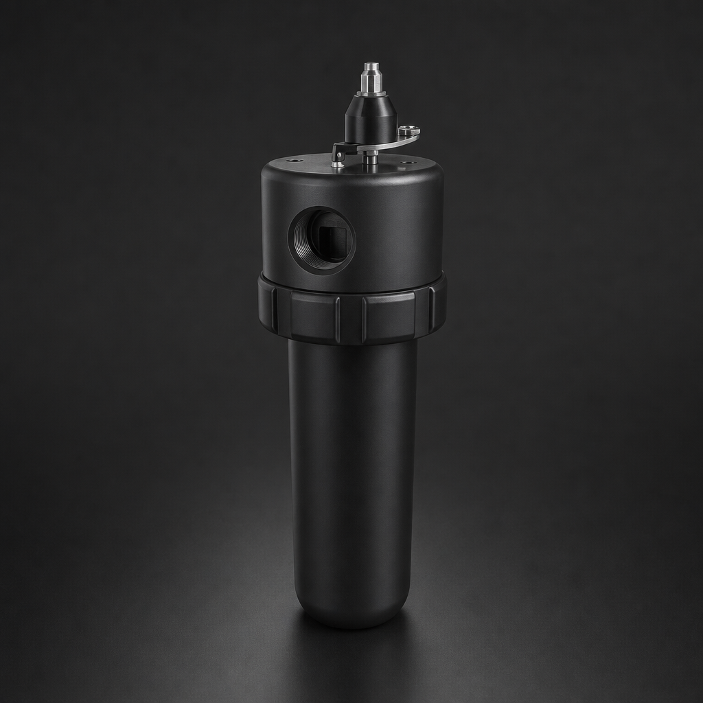
Coalescing filters are the workhorse of compressed gas purification — but even the best coalescing element will fail prematurely if bulk liquid is allowed to flood it from below. Two often-overlooked accessories solve this problem elegantly: the catchpot and the drain vessel. Understanding when and why to use each one can mean the difference between a filter system that runs reliably for years and one that requires constant attention.
The Two Problems Catchpots and Drain Vessels Solve
Before specifying any coalescing filter system, it is worth understanding the two distinct liquid-management challenges that arise in compressed gas lines:
- Bulk liquid ingress: Slugs or surges of liquid — water, oil, or condensate — can arrive at the filter housing from upstream pipework, particularly after compressor start-up, during pressure swings, or in poorly drained distribution systems. If this bulk liquid reaches the coalescing element directly, it saturates the microfibre matrix, causes a sharp rise in differential pressure, and can result in liquid carry-over downstream.
- Bowl drainage frequency: Even without bulk liquid slugs, a coalescing filter accumulates liquid in its bowl over time. In high-flow or high-humidity applications, the bowl can fill rapidly, requiring frequent manual drainage or a reliable automatic drain — otherwise the liquid level rises until it re-entrains into the gas stream.
Catchpots address the first problem. Drain vessels address the second. In demanding applications, both are used together. You can explore the full range of compressed air filter housings and accessories available from R+F FilterElements to build a complete liquid-management solution.
How a Catchpot Works
A catchpot — sometimes called a bulk liquid separator or pre-separator — is installed immediately upstream of the coalescing filter housing. Its operating principle is straightforward: the incoming gas stream is forced to change direction sharply as it enters the catchpot vessel. The momentum of liquid droplets and slugs carries them to the vessel wall and downward into the sump, while the lighter gas continues upward and exits to the coalescing filter.
This inertial separation mechanism is highly effective for droplets larger than approximately 10–50 µm. It does not remove fine aerosols — that remains the job of the coalescing filter element — but it reliably intercepts the bulk liquid that would otherwise overwhelm the element. The result is a coalescing filter that sees only the fine aerosol fraction it was designed to handle, operating at its rated efficiency and pressure drop throughout its service life.
Drain Vessel Options: Direct-Mount vs. Valve-Isolated
Once liquid has been separated — whether by a catchpot or by the coalescing element itself — it must be removed from the system reliably. This is where drain vessels come in. There are two principal configurations:
Direct-Mount Drain Vessels
A direct-mount drain vessel threads or flanges directly onto the drain port of the filter housing bowl, effectively extending the bowl's liquid-holding capacity. Gas pressure in the filter housing acts directly on the liquid in the drain vessel, which means the vessel is always at line pressure. Drainage is achieved by opening a manual valve or automatic float drain at the base of the vessel.
Direct-mount vessels are the simplest and most common solution for standard compressed air applications. They are well-suited to systems where the gas is non-toxic, non-flammable, and where some gas loss during drainage is acceptable.
Valve-Isolated Drain Vessels
In applications involving low-pressure systems, low liquid volumes, or — critically — hazardous gases such as hydrogen, natural gas, or toxic process gases, gas loss during drainage must be minimised. A valve-isolated drain vessel addresses this by incorporating an isolation valve between the filter housing and the drain vessel.
The operating sequence is: (1) the isolation valve opens to allow liquid to flow from the filter bowl into the drain vessel; (2) the isolation valve closes, trapping the liquid in the drain vessel at line pressure; (3) the drain valve at the base of the vessel opens to discharge the liquid — releasing only the small volume of gas trapped in the drain vessel, not the full system pressure. This approach is standard practice in process gas and instrumentation applications. See our guide on how coalescing filters work for more background on liquid separation mechanisms.
Need help selecting the right filter accessories?
Use our free Engineering Tool to get a filtration recommendation for your specific application in under 2 minutes.
Drainage Methods: Manual, Automatic, and Continuous
Regardless of whether a direct-mount or valve-isolated drain vessel is used, the liquid must ultimately be discharged. Three drainage methods are available:
| Drainage Method | How It Works | Best For | Gas Loss |
|---|---|---|---|
| Manual valve | Operator opens drain valve periodically | Low liquid volumes, infrequent drainage | Moderate (operator-dependent) |
| Automatic float drain | Float rises with liquid level, opens drain valve automatically | High liquid volumes, unattended operation | Low (drains only when liquid present) |
| Continuous drain connection | Drain port connected to a collection system or drain line | Very high liquid volumes, process integration | Depends on system design |
Automatic float drains are the preferred choice for most industrial compressed air systems, as they eliminate the risk of bowl overflow due to operator oversight. For process gas applications where gas loss must be minimised, a valve-isolated drain vessel with a manual or timed drain valve is typically specified.
R+F FilterElements Coalescing Housings and Accessories
R+F FilterElements offers a comprehensive range of coalescing filter housings suitable for use with catchpots and drain vessels. The RF-H-310 to RF-H-395 series covers compressed air applications from small point-of-use installations up to large central systems handling 12,000 Nm³/h at up to 17 bar. These housings accept RF-C coalescing elements — borosilicate glass microfibre elements rated at 99.99% efficiency for aerosols ≥ 0.1 µm — as well as RF-P particulate elements for pre-filtration duty.
For process gas and high-pressure applications, the RF-H-150 and RF-H-160 housings in 316L stainless steel are available with drain ports configured for valve-isolated drain vessels. The RF-H-150 is rated to 100 bar; the RF-H-160 to 250 bar — both suitable for natural gas, hydrogen, and other process gases where liquid management is critical.
When specifying a complete coalescing filter system, R+F FilterElements recommends considering the full liquid-management train: catchpot → coalescing filter → drain vessel → drainage method. Each component should be sized consistently for the same flow rate and pressure. Visit the filter elements product page to explore the full RF-C and RF-P element range.
- Bowl drainage frequency:
- A catchpot — sometimes called a bulk liquid separator or pre-separator — is installed immediately upstream of the coalescing filter housing.
- Once liquid has been separated — whether by a catchpot or by the coalescing element itself — it must be removed from the system reliably.
- Automatic float drain
Sizing Considerations
Catchpots and drain vessels must be sized to match the flow capacity of the coalescing filter housing. An undersized catchpot will have insufficient residence time for inertial separation, allowing bulk liquid to pass through. An undersized drain vessel will fill rapidly and require frequent drainage cycles, negating its purpose.
Key sizing parameters include: maximum gas flow rate (Nm³/h or m³/h free air), operating pressure (bar g), expected liquid load (litres per hour or per shift), and drainage interval. For hazardous gas applications, the drain vessel volume should be calculated to hold at least one full drainage cycle's worth of liquid without requiring the isolation valve to be opened more than once per shift.
R+F FilterElements' engineering team can assist with sizing calculations for complete coalescing filter systems, including catchpot and drain vessel selection. Use the Engineering Sizing Tool for an initial specification, or contact us directly for complex or hazardous gas applications.
Related Reading
- How Coalescing Filters Work — Principles and Selection Guide
- Coalescing vs Particulate Filter Elements — Which Do You Need?
- ISO 8573-1 Compressed Air Quality Classes Explained
Try our Engineering Sizing Tool → or discuss your requirements with our team.

