The last metre is the weakest link
You have invested in a properly sized compressor-room filtration system: coalescing filters, particulate filters, dryers, perhaps even an adsorber for oil-vapour removal. The gas leaving the treatment train meets ISO 8573-1 Class 1.2.1 — in theory. But what happens between that central treatment point and the actual point of use, 50, 100, or 500 metres away?
Distribution piping introduces contamination that no central filter can prevent. Pipe scale from corrosion, thread sealant particles dislodged during maintenance, condensate that forms in unlagged outdoor runs, and even microbial colonies that colonise stagnant dead-legs — all of these degrade the gas quality between the compressor room and the point of use.
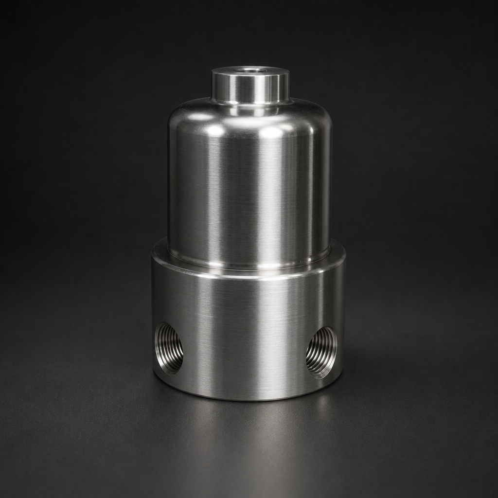
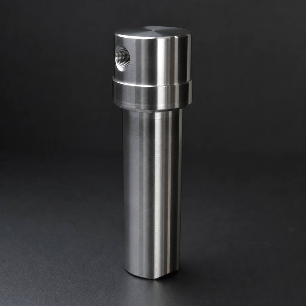
Final filtration — sometimes called “point-of-use” or “last-metre” filtration — addresses this gap. A compact inline filter installed within the last metre of piping before the application ensures that the gas actually arriving at the machine, instrument, or process meets specification. Every time.
Key Takeaway
- Central filtration protects the distribution network. Point-of-use filtration protects the application.
- Distribution piping is a contamination source, not just a transport medium — pipe scale, condensate, and thread debris are inevitable over time.
- A compact inline filter at the point of use is the most cost-effective insurance against process disruption caused by piping-born contamination.
Where does distribution-piping contamination come from?
Pipe Scale and Corrosion Products
Carbon-steel piping corrodes internally, shedding iron-oxide particles (rust). Even stainless-steel or aluminium systems generate fine particulate from weld spatter, burrs left after cutting, and galvanic corrosion at dissimilar-metal joints.
Condensate Formation
Temperature drops along uninsulated pipe runs cause moisture to condense — even if the gas left the dryer well below its pressure dew point. A 10 °C ambient temperature swing on an outdoor pipe run can push a −20 °C PDP gas into condensation territory at the pipe wall.
Thread Sealant and Installation Debris
PTFE tape fragments, pipe-dope residue, and metal swarf from threading or welding are released into the gas stream during installation or after maintenance. These particles are often large (>50 µm) but can damage sensitive valve seats or instrument orifices.
Microbial Growth in Dead-Legs
Stagnant pipe sections — tee connections, unused branch lines, pressure-gauge connections — accumulate moisture and become breeding grounds for bacteria and biofilm. Intermittent flow flushes these colonies downstream to the point of use.
What point-of-use filters actually do
A point-of-use filter is not a replacement for central treatment. It is the final safety net — a compact, low-cost device that removes the contamination introduced after central treatment. Its function depends on the application:
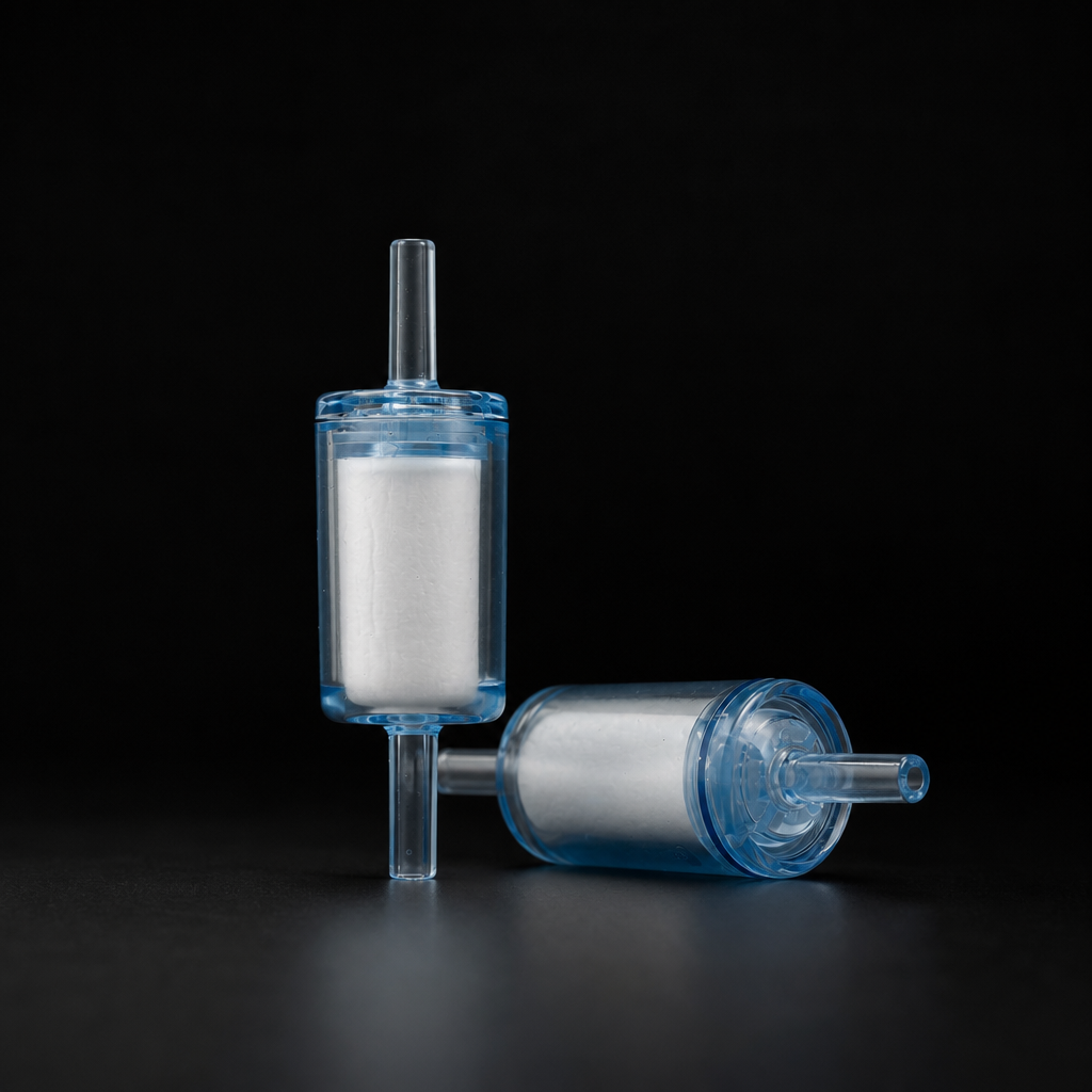
- Particulate protection — A 1–5 µm sintered-metal or pleated-media element captures pipe scale, rust, and installation debris. This is the minimum standard for pneumatic valve actuators, cylinders, and blowdown nozzles.
- Coalescing protection — A 0.01 µm coalescing element removes re-entrained oil mist and fine condensate aerosol. Required for spray-painting, food-contact air, and instrument supply.
- Sterile barrier — A 0.2 µm PTFE membrane blocks bacteria and microorganisms. Mandatory for pharmaceutical gas supplies, fermentation, and cleanroom environments.
Cost perspective
A point-of-use inline filter typically costs less than a single hour of unplanned downtime on the machine it protects. For a CNC machining centre, paint booth, or analytical instrument, the filter investment pays for itself with the first contamination event it prevents.
Where to install point-of-use filters
The placement rule is simple: as close to the application as physically possible, ideally within the last metre of piping. Specific recommendations:
- Analytical instruments — Directly at the sample-gas inlet. Use a 0.5 µm or finer element to protect capillary tubing and detector cells. See our guide to protecting analytical instruments.
- Pneumatic actuators and valves — At the solenoid-valve inlet manifold. A 5 µm element is usually sufficient to protect spool valves from particle-induced stiction.
- Spray-painting and food-contact air — At the spray-gun connection or the air-entry point to the packaging line. Use a coalescing grade (0.01 mg/m³ residual oil) to prevent product contamination.
- Sterile process gas — At the vessel inlet or bioreactor sparge point. Use a validated 0.2 µm sterilising-grade filter with integrity-test capability. Read more in our sterile filtration guide.
Maintenance is minimal
Point-of-use filters are designed for low maintenance. Typical service intervals are 6–12 months for particulate elements and 12–24 months for sterile membranes in clean-gas service. Monitor differential pressure and replace when ΔP reaches the manufacturer's recommended change-out threshold.
Choosing the right point-of-use filter
Selection depends on three factors:
- Contamination type — Particles only? Aerosols? Microorganisms? This determines the element type (particulate, coalescing, or membrane).
- Flow rate — Point-of-use flows are typically low (1–50 Nm³/h). Our RF-DIL inline series covers this range in a compact body with standard ¼″ to 1″ connections.
- Connection type — Match the filter connections to the existing piping. Threaded (NPT/BSP), compression (Swagelok-type), and tri-clamp options are available.
Protect the last metre of your gas system
Browse our range of compact inline filters designed for point-of-use installation. Use the Engineering Tool to select the right grade and size for your application.
Related reading
- Filter Placement in Compressor Systems — Where central filters belong in the treatment train.
- Filter Blocking: Troubleshooting Guide — Diagnose why point-of-use filters are blocking faster than expected.
- Compressed Air Filters — Central filtration solutions for the compressor room.