Why Liquid Aerosols Are a Problem in Gas Systems
Every compressed air or process gas system carries some quantity of liquid contamination — oil aerosol from compressor lubrication, water condensate, or hydrocarbon mist from upstream processes. At sub-micron droplet sizes these aerosols behave like a gas: they pass straight through standard particulate filters, foul instrumentation, corrode pipework, and contaminate downstream processes. A coalescing filter is the engineered solution to this problem.
The Coalescence Principle — How It Works
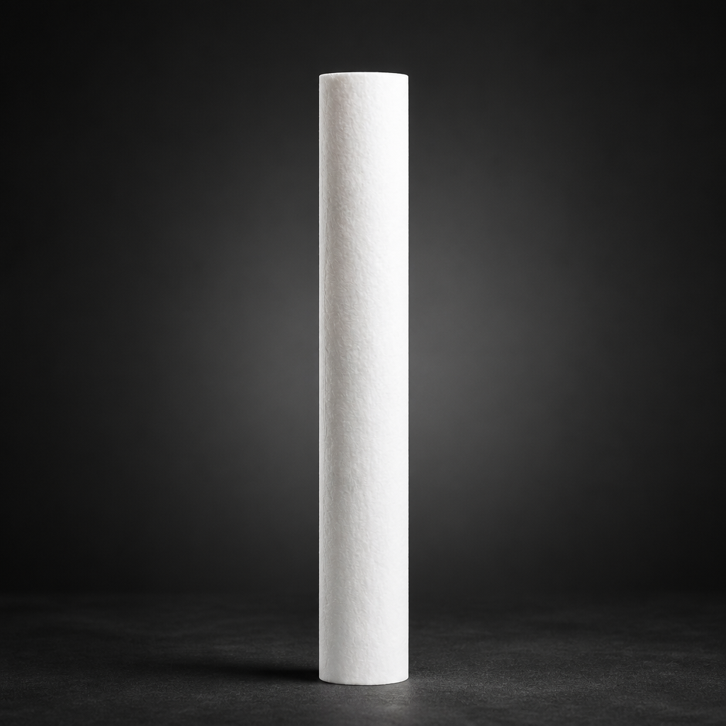
Coalescence (German: Koaleszenz) describes the merging of small droplets into progressively larger ones. In a coalescing filter element, the gas stream passes through a tightly packed bed of borosilicate glass microfibres with diameters typically between 0.5 µm and 6 µm. Three capture mechanisms act simultaneously:
- Interception: Droplets following a streamline make contact with a fibre surface and adhere.
- Inertial impaction: Larger droplets (> 1 µm) cannot follow the curved streamline around a fibre and impact directly.
- Diffusion: Very small droplets (< 0.3 µm) undergo Brownian motion, increasing the probability of fibre contact.
Once captured, droplets wet the fibre surface and migrate along it until they meet another droplet. The two merge — coalesce — into a larger drop. This process repeats until the drop is large enough for gravity to overcome surface tension, at which point it drains downward into the sump at the base of the housing.
The efficiency of this process depends on three design parameters: fibre diameter (finer fibres capture smaller droplets), packing density (higher density increases contact probability but also pressure drop), and face velocity (lower velocity gives droplets more time to coalesce before being re-entrained). R+F RF-C coalescing elements are engineered to balance all three for optimal performance across the rated flow range.
Filter Construction — From Inner to Outer
A coalescing filter element is a cylindrical structure with gas flowing from the inside (dirty side) to the outside (clean side). This inside-to-outside flow direction is critical: it ensures that coalesced liquid drains downward by gravity rather than being carried forward into the clean gas stream.
The construction layers, from innermost to outermost, are:
- Perforated inner core: Provides structural support and distributes gas flow evenly across the element face.
- Pre-filter layer: A coarser fibre layer that captures bulk liquid and larger particles, protecting the main coalescence layer.
- Coalescence layer: The primary borosilicate microfibre bed where sub-micron aerosol capture and droplet merging occur.
- Drainage layer: A hydrophobic outer wrap that allows coalesced liquid to drain freely while preventing re-entrainment of droplets into the clean gas.
- Outer support cage: Maintains element geometry under differential pressure.
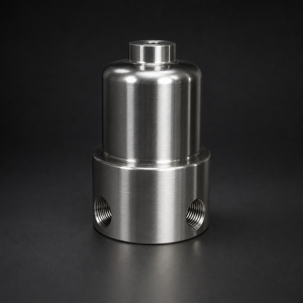
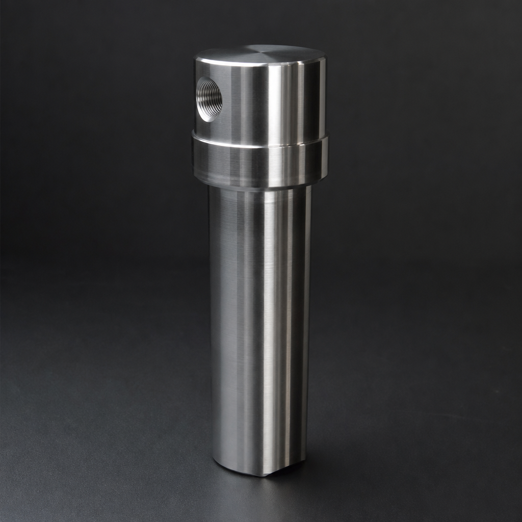
The housing itself includes a drain sump at the bottom where collected liquid accumulates. Automatic float drains or manual drain valves remove this liquid without interrupting gas flow. For process gas applications, the RF-H-150 housing (100 bar, 316L stainless steel) is a compact and robust choice that pairs directly with RF-C elements.
Performance Metrics and ISO 12500-1
Coalescing filter performance is standardised under ISO 12500-1, which defines test methods for oil aerosol removal efficiency in compressed air. The key metric is residual aerosol concentration at the filter outlet, measured in mg/m³ at reference conditions (20 °C, 1 bar absolute).
For compressed air quality classification, ISO 8573-1 Class 1 for oil aerosol (≤ 0.01 mg/m³) requires a high-efficiency coalescing stage. The ISO 8573-1 guide on this blog explains how to select the correct filter class for your application.
Need help selecting the right coalescing filter?
Use our free Engineering Tool to get a filtration recommendation for your specific application in under 2 minutes.
Applications in Gas Filtration
Compressed Air Systems
Oil-injected rotary screw compressors introduce oil aerosol at concentrations of 2–10 mg/m³ into the compressed air stream. A coalescing filter stage — typically an RF-C element in an RF-H-310 to RF-H-395 series housing — reduces this to ≤ 0.01 mg/m³, protecting downstream equipment and meeting ISO 8573-1 Class 1 requirements.
Process Gas and Hydrogen
In hydrogen production and distribution, compressor oil contamination must be removed before the gas enters fuel cells, electrolysers, or analytical instruments. The RF-H-150 housing with RF-C elements handles pressures up to 100 bar in 316L stainless steel construction, making it suitable for high-purity hydrogen service. For higher pressures, the RF-H-160 (250 bar) and RF-H-170 (400 bar) housings extend coverage to the most demanding hydrogen applications.
Vacuum Pump Exhaust
Oil-sealed vacuum pumps exhaust a fine oil mist that must be captured before the gas is vented to atmosphere or recirculated. Vacuum exhaust coalescing filters operate at near-atmospheric pressure on the outlet side, requiring elements with low pressure drop. The RF-H-420 to RF-H-456 series housings, paired with RF-CS vacuum elements, are designed specifically for this duty. See the vacuum pump exhaust filter range for sizing data.
Natural Gas and Biogas
Compressor lubricants and condensed hydrocarbons in natural gas and biogas pipelines can foul metering equipment and catalysts. Coalescing filtration upstream of gas meters, analysers, and burners protects these assets and extends service intervals. The natural gas filtration solutions page covers recommended filter configurations for these duties.
Comparison with Alternative Liquid-Separation Methods
| Method | Minimum droplet size | Residual aerosol | Pressure drop | Best suited for |
|---|---|---|---|---|
| Cyclone separator | ~10 µm | ~1–5 mg/m³ | Low | Bulk liquid removal, pre-separation |
| Demister mesh | ~5 µm | ~0.5–2 mg/m³ | Very low | Vessel internals, large flow rates |
| Coalescing filter (RF-C) | 0.1 µm | ≤ 0.01 mg/m³ | Medium | Sub-micron aerosol removal, ISO 8573-1 Class 1 |
| Membrane separator (RF-GMS-170) | Absolute liquid barrier | Zero liquid carry-over | Low–medium | Absolute liquid exclusion, slug flow protection |
In practice, a two-stage approach is most effective: a cyclone or demister mesh as a pre-separator to handle bulk liquid slugs, followed by a coalescing filter for sub-micron aerosol polishing. For applications where even trace liquid carry-over is unacceptable, a membrane separator such as the RF-GMS-170 can be added as a final guard stage.
For a detailed comparison of coalescing and particulate filter elements, see the coalescing vs particulate filter elements guide on this blog.
- Coalescence (German: Koaleszenz) describes the merging of small droplets into progressively larger ones.
- Perforated inner core:
- residual aerosol concentration
- Oil-injected rotary screw compressors introduce oil aerosol at concentrations of 2–10 mg/m³ into the compressed air stream.
Selecting the Right Coalescing Filter
Key parameters for filter selection are: operating pressure, flow rate (Nm³/h), inlet oil aerosol concentration, required outlet quality (ISO 8573-1 class), and gas temperature. R+F FilterElements offers its own range of RF-C coalescing elements in six standard sizes (12032, 12057, 25064, 25178, 51230, 51476) covering flows from a few Nm³/h up to 12,000 Nm³/h per housing. For high-pressure process gas duties, the RF-H-150 housing (100 bar) accepts RF-C elements and is available from R+F FilterElements in 316L stainless steel with FKM or PTFE seals.
Use the R+F Engineering Sizing Tool to match element size and housing to your specific flow and pressure conditions, or consult the coalescence filters explained reference article for additional technical background.
Related Reading
- Coalescing vs Particulate Filter Elements — Which Do You Need?
- ISO 8573-1 Compressed Air Quality — A Practical Guide
- Filtration Requirements for Hydrogen Electrolysis Systems
Try our Engineering Sizing Tool → or discuss your requirements with our team.