
Warum Elektrolyt-Verschleppung eine verborgene Gefahr bei der alkalischen Elektrolyse darstellt
Die alkalische Wasserelektrolyse ist eine der etabliertesten Methoden zur Erzeugung von grünem Wasserstoff. Die Zellen arbeiten mit einem konzentrierten Kaliumhydroxid-Elektrolyten (KOH) — typischerweise 25–30 Gew.-% — bei Temperaturen zwischen 60 °C und 90 °C. Unter diesen Bedingungen erzeugt die intensive Gasentwicklung an beiden Elektroden ein feines Aerosol aus KOH-Tröpfchen, das in den Produktwasserstoffstrom mitgerissen wird. Dieses Phänomen, bekannt als Elektrolyt-Verschleppung, ist keine geringfügige Störung: Es handelt sich um eine fortschreitende, korrosive Bedrohung für jede Anlagekomponente, die dem Elektrolyseurstack nachgeschaltet ist.
Wird das Problem nicht behoben, greift KOH-Nebel Kohlenstoffstahlrohrleitungen an, verursacht Spannungsrisskorrosion in bestimmten Edelstahllegierungen, blockiert Sicherheitsventile, schädigt Ventilsitze in Verdichtern und kontaminiert Wasserstoffspeicherbehälter. In Systemen, die Brennstoffzellen oder Industrieprozesse mit strengen Reinheitsanforderungen versorgen, kann selbst eine Spurenkontamination mit Elektrolyt den Wasserstoff unbrauchbar machen. Dennoch unterschätzen viele Betreiber das Problem — oder versuchen, es mit handelsüblichen Druckluftfiltern zu lösen, die für den kaustischen Betrieb völlig ungeeignet sind.
Dieser Artikel erläutert die Mechanismen der KOH-Aerosolbildung, warum Standard-Filterelemente versagen und wie eine korrekt ausgelegte zweistufige Filtrationsstrecke mit chemisch beständigen K-Typ-Elementen einen zuverlässigen, langlebigen Schutz bietet.
Wie KOH-Aerosol im Elektrolyseur entsteht
In einer alkalischen Elektrolyseurzelle wird Wasserstoff an der Kathode und Sauerstoff an der Anode entwickelt. Die intensive Keimbildung und das Ablösen von Gasblasen von den Elektrodenoberflächen erzeugen eine turbulente Zweiphasenströmung im Elektrolyten. Wenn Blasen an der Gas-Flüssigkeits-Grenzfläche platzen, schleudern sie winzige KOH-Lösungströpfchen in den darüber liegenden Gasraum. Die Tröpfchengrößenverteilung umfasst einen weiten Bereich — von großen Tröpfchen (>10 µm), die schnell absinken, bis hin zu submikronen Aerosolpartikeln, die nahezu unbegrenzt im Gasstrom suspendiert bleiben.
Mehrere Betriebsparameter verstärken die Verschleppung:
- Höhere Stromdichte — intensivere Gasentwicklung, stärkere Aerosolbildung
- Erhöhte Temperatur — geringere Oberflächenspannung, kleinere und beständigere Tröpfchen
- Höhere Gasgeschwindigkeit — verstärktes Mitreißen von Tröpfchen von der Flüssigkeitsoberfläche
- Schaumbildung — verursacht durch organische Verunreinigungen oder Elektrolyt-Abbauprodukte
Moderne Hochleistungselektrolyseure, die bei erhöhten Stromdichten betrieben werden, um die Investitionskosten pro Kilowatt zu senken, sind daher besonders anfällig für Verschleppung. Das den Elektrolyseurstack verlassende Gas durchläuft in der Regel einen internen Gas-Flüssigkeits-Abscheider, der jedoch nur die gröberen Tröpfchen entfernt. Feines Aerosol — der Anteil, der für nachgeschaltete Anlagen am schädlichsten ist — passiert diesen ungehindert.
Warum Standard-Filterelemente im KOH-Betrieb versagen
Der häufigste Fehler bei der Auslegung der Filtration für die alkalische Elektrolyse besteht darin, auf einen handelsüblichen Druckluft-Koaleszenzfilter zurückzugreifen. Diese Elemente werden aus Borosilikatglas-Mikrofasern hergestellt, die mit einem Epoxid- oder Phenolharz-Bindemittel gebunden sind. Im trockenen oder leicht feuchten Druckluftbetrieb ist diese Konstruktion hervorragend geeignet. In einer 25–30 Gew.-%igen KOH-Umgebung bei 70–90 °C ist sie jedoch katastrophal falsch.
Konzentriertes Kaliumhydroxid ist stark alkalisch (pH >14) und greift Borosilikatglas durch Netzwerkauflösung an. Der Siliziumdioxid-Anteil (SiO₂) des Glases reagiert mit Hydroxidionen zu löslichen Silikatverbindungen und zerstört dabei die Faserstruktur fortschreitend. Gleichzeitig werden viele Harzbindemittel durch heiße Kaugsodlösung hydrolysiert, was zur Delamination des Elements und zum Eintrag von Fasern in den Gasstrom führt. Das Ergebnis ist ein rascher Verlust des Abscheidegrads, ein struktureller Kollaps des Elements und eine Kontamination des nachgeschalteten Systems — das genaue Gegenteil des angestrebten Schutzes.
Gehäusewerkstoffe stellen eine parallele Herausforderung dar. Standard-Aluminiumfiltergehäuse werden von KOH bereits bei moderaten Konzentrationen angegriffen. Polycarbonat-Behälterschaugläser lösen sich auf. Nur 316L-Edelstahl — oder höherwertige Legierungen — bietet im alkalischen Elektrolysebetrieb ausreichende Korrosionsbeständigkeit.
Das K-Typ-Element: Entwickelt für kaustische Umgebungen
R+F FilterElements bietet eine eigene Reihe von K-Typ-Filterelementen an, die speziell für den Einsatz mit Sauergas, kaustischen Medien und chemisch aggressiven Prozessen entwickelt wurden. Im Gegensatz zu Standard-Elementen verwenden K-Typ-Elemente eine chemisch inerte Fasermatrix — frei von Borosilikatglas — in Kombination mit einem PTFE-basierten Bindersystem, das sowohl starken Säuren als auch starken Laugen widersteht. Das Ergebnis ist ein Element, das seine strukturelle Integrität und seinen Abscheidegrad über die gesamte Standzeit im KOH-Betrieb beibehält.
K-Typ-Elemente sind sowohl in Koaleszenz- als auch in Partikelfilter-Ausführung erhältlich und decken die beiden unterschiedlichen Abscheideaufgaben ab, die in einer alkalischen Elektrolyse-Filtrationsstrecke erforderlich sind:
- K-Typ-Koaleszenzelemente (RF-C-K-Serie) — fangen flüssige KOH-Aerosoltröpfchen ab und koaleszieren diese, die dann in einen Sammelbehälter ablaufen und periodisch entfernt werden
- K-Typ-Partikelfilterelemente (RF-P-K-Serie) — entfernen feste KOH-Partikel und verbleibende feine Aerosole, die in der Koaleszenzstufe nicht abgeschieden wurden
Beide Typen sind in den Standard-R+F-Elementgrößen (12032, 12057, 25064, 25178, 51230, 51476) erhältlich und können in die entsprechenden Prozessgas-Filtergehäuse der RF-H-150- und RF-H-160-Serie eingebaut werden.
Verwendung von Standard-Druckluftfiltern:
Auslegung der zweistufigen Filtrationsstrecke
Eine wirksame KOH-Nebelabscheidung erfordert zwei komplementäre, in Reihe geschaltete Stufen. Ein einstufiger Ansatz — ob Koaleszenz- oder Partikelfiltration allein — kann die für den Schutz nachgeschalteter Anlagen oder für Wasserstoff-Qualitätsspezifikationen erforderlichen Reinheitsgrade nicht zuverlässig erreichen.
Stufe 1: Koaleszenzabscheidung
Die erste Stufe zielt auf flüssiges KOH-Aerosol ab. Das Gas tritt von außen in das Koaleszenzelement ein und strömt durch die Fasermatrix nach innen. Feine Tröpfchen werden durch Trägheitsabscheidung, Sperreffekt und Diffusion abgefangen. Wenn sich Tröpfchen auf den Fasern ansammeln, koaleszieren sie zu größeren Tropfen, die unter Schwerkraft in den Gehäusesammelbehälter ablaufen. Der Sammelbehälter ist mit einem automatischen Schwimmerableiter ausgestattet, der die gesammelte Flüssigkeit entfernt, ohne den Gasfluss zu unterbrechen.
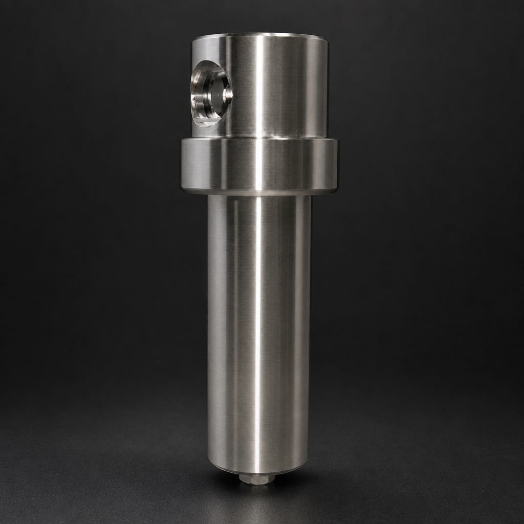
Für diese Aufgabe empfiehlt R+F das Gehäuse RF-H-152 — ein kompaktes Prozessgas-Filtergehäuse aus 316L-Edelstahl mit einer Druckauslegung bis 100 bar — bestückt mit K-Typ-Koaleszenzelementen. Das RF-H-152 ist mit FKM (Viton)-O-Ring-Dichtungen erhältlich, die eine ausgezeichnete Beständigkeit gegenüber heißer KOH-Lösung bieten und für diese Anwendung zwingend vorgeschrieben sind. NBR-Dichtungen dürfen nicht verwendet werden, da sie im kaustischen Betrieb schnell quellen und sich zersetzen.
Stufe 2: Abschließende Partikelfiltration
Die zweite Stufe scheidet verbleibende feste KOH-Partikel und submikrone Aerosole ab, die die Koaleszenzstufe passiert haben. Feste Partikel entstehen durch Kristallisation von KOH an kälteren Oberflächen in der Rohrleitung oder durch eingetrocknete Aerosoltröpfchen. Ein K-Typ-Partikelfilterelement mit einem Abscheidegrad von 99,99 % bei ≥0,3 µm bildet die abschließende Barriere, bevor das Gas in die Verdichtung oder Speicherung gelangt.
Für diese Stufe ist das Gehäuse RF-H-160 — ausgelegt bis 250 bar in 316L-Edelstahl — geeignet, wenn höhere Betriebsdrücke nach einem Nachverdichter auftreten. Auch hier sind FKM-Dichtungen zwingend vorgeschrieben.
Vollständige Spezifikation der Filtrationsstrecke
| Parameter | Stufe 1 — Koaleszenz | Stufe 2 — Partikelfiltration |
|---|---|---|
| Gehäusemodell | RF-H-152 | RF-H-160 |
| Gehäusewerkstoff | 316L-Edelstahl | 316L-Edelstahl |
| Max. Betriebsdruck | 100 bar | 250 bar |
| Max. Betriebstemperatur | 200 °C (S-Typ) / 100 °C (Standard) | 200 °C (S-Typ) / 100 °C (Standard) |
| Elementtyp | RF-C-K (K-Typ Koaleszenz) | RF-P-K (K-Typ Partikelfilter) |
| Abscheidegrad | 99,99 % ≥ 0,1 µm flüssig | 99,99 % ≥ 0,3 µm partikulär |
| Dichtungswerkstoff | FKM (Viton) — zwingend erforderlich | FKM (Viton) — zwingend erforderlich |
| Ableiter | Automatischer Schwimmerableiter | Manueller oder zeitgesteuerter Automatikableiter |
| Anschlüsse | ¼″ bis 1½″ BSP/NPT | ¼″ bis 1½″ BSP/NPT |
Positionierung der Filtrationsstrecke im Prozess
Die Filtrationsstrecke sollte unmittelbar nach dem internen Gas-Flüssigkeits-Abscheider des Elektrolyseurs und vor jeder Verdichterstufe installiert werden. Diese Positionierung ist aus zwei Gründen entscheidend. Erstens befindet sich das Gas an diesem Punkt bei relativ niedrigem Druck (typischerweise 1–30 bar, je nach Elektrolyseurausführung), was bedeutet, dass die Aerosoltröpfchen größer und leichter zu koaleszieren sind. Zweitens ist der Schutz des Verdichters vor KOH-Eintrag von größter Bedeutung — Verdichtereinbauten sind nach einer Kontamination äußerst schwierig und kostspielig zu reinigen oder zu ersetzen.
Wenn ein Nachverdichter den Wasserstoffdruck auf Speicher- oder Leitungsdruck anhebt (typischerweise 200–700 bar), ist eine zweite Partikelfiltrationsstufe nach dem Verdichter empfehlenswert, um feste Partikel abzuscheiden, die durch den Verdichtungsprozess selbst entstehen. Die Gehäuse RF-H-160 oder RF-H-170 sind für diesen Hochdruckbetrieb geeignet.
Betreiber sollten auch die vollständige Wasserstofffiltrationslösung von R+F FilterElements in Betracht ziehen, die den gesamten Druckbereich vom Elektrolyseurausgang bis zur Hochdruckspeicherung abdeckt, einschließlich der Sauerstoffseitenfiltration mit EPDM-O₂-gedichteten Gehäusen.
Use our free Engineering Tool to get a filtration recommendation for your specific application in under 2 minutes.
Dichtungs- und Werkstoffauswahl: Ein kritisches Detail
Die Werkstoffverträglichkeit im KOH-Betrieb geht über das Filterelement selbst hinaus. Jede medienberührte Komponente — Gehäusekörper, Endkappen, Ablassventile, Druckmessgeräte und Verbindungsrohrleitungen — muss auf Laugenbeständigkeit geprüft werden. Folgende Hinweise gelten:
- Gehäusekörper: Mindestens 316L-Edelstahl; Duplex-Edelstahl für höhere Temperaturen oder höhere Konzentrationen
- O-Ring-Dichtungen: FKM (Viton) bis 200 °C; PTFE-ummantelte Dichtungen für extreme Bedingungen
- Ablassventile: Gehäuse aus 316L-Edelstahl mit PTFE-gedichteten Kugelventilen
- Druckmessgeräte: Glyzerinfüllung mit medienberührten Teilen aus 316L-Edelstahl und Membranabdichtung
- Rohrleitungen: Durchgehend 316L-Edelstahl; Kohlenstoffstahl, Kupfer und Aluminium sind zu vermeiden
NBR (Nitril)-Dichtungen — der Standard in vielen handelsüblichen Filtergehäusen — dürfen im KOH-Betrieb keinesfalls verwendet werden. NBR quillt in konzentrierter Lauge erheblich auf, was zu Dichtungsextrusion, Leckagen und möglichem Gehäuseversagen führt. EPDM-Dichtungen sind zwar chemisch beständig gegenüber KOH, werden jedoch nicht empfohlen, wenn der Gasstrom Spuren von Kohlenwasserstoffen oder Schmiermitteln aus der Verdichterstufe enthalten kann.
Leistungsüberwachung und Bestimmung der Wechselintervalle
Anders als bei der Druckluftfiltration, wo Elementwechselintervalle häufig allein nach Betriebszeit festgelegt werden, erfordert der alkalische Elektrolysebetrieb einen aktiveren Überwachungsansatz. Die KOH-Beladung der Filterelemente variiert mit den Betriebsbedingungen des Elektrolyseurs, und ein stark beladenes Element kann seine Druckverlustgrenze weit vor dem Zeitpunkt erreichen, den ein zeitbasiertes Intervall anzeigen würde.
R+F empfiehlt die Installation eines Differenzdruckanzeigers über jede Filterstufe. Ein ansteigender Differenzdruck zeigt die Elementbeladung und das nahende Lebensende an. Typische Wechselkriterien:
- Differenzdruck über der Koaleszenzstufe überschreitet 0,5 bar
- Differenzdruck über der Partikelfiltrationsstufe überschreitet 0,3 bar
- Sichtbare KOH-Kristallisation auf den Außenflächen des Gehäuses (Hinweis auf Dichtungsleckage)
- Geplantes Wartungsintervall — typischerweise 4.000–6.000 Betriebsstunden im Dauerbetrieb
Beim Elementwechsel sollten Betreiber geeignete PSA tragen — chemikalienbeständige Handschuhe, Augenschutz und Gesichtsschutz — da verbrauchte Elemente mit konzentrierter KOH-Lösung gesättigt sind. Verbrauchte Elemente sind gemäß den örtlichen Vorschriften für kaustische Abfälle zu entsorgen.
Zur Auslegung der richtigen Gehäuse- und Elementkombination für einen bestimmten Elektrolyseur-Volumenstrom stellt R+F FilterElements einen Online-Auslegungsassistenten bereit, der Gaszusammensetzung, Druck, Temperatur und die geforderte Ausgangsqualität berücksichtigt.
Häufige Fehler und wie man sie vermeidet
Basierend auf Anfragen, die R+F FilterElements von Betreibern alkalischer Elektrolysesysteme erhalten hat, treten folgende Fehler wiederholt auf:
- Verwendung von Standard-Druckluftfiltern: Wie erläutert, lösen sich Borosilikatglas-Elemente in KOH auf. K-Typ-Elemente müssen stets ausdrücklich spezifiziert werden.
- Nur einstufige Filtration: Eine Koaleszenzstufe allein entfernt keine festen KOH-Partikel; eine abschließende Partikelfiltrationsstufe ist stets erforderlich.
- Aluminiumgehäuse: Aluminium wird von KOH bereits bei niedrigen Konzentrationen angegriffen. 316L-Edelstahl ist der minimal akzeptable Werkstoff.
- Falscher Dichtungswerkstoff: NBR-Dichtungen versagen schnell. FKM- oder PTFE-Dichtungen sind zwingend erforderlich.
- Filtration nur nach dem Verdichter: Der Verdichter muss vor KOH-Eintrag geschützt werden. Die Filtration muss vor dem Verdichtereinlass installiert werden.
- Vernachlässigung der Sauerstoffseite: Der Sauerstoffstrom eines alkalischen Elektrolyseurs enthält ebenfalls KOH-Aerosol und erfordert eine gleichwertige Filtration mit EPDM-O₂-kompatiblen Dichtungen.
- Höhere Gasgeschwindigkeit
- Der häufigste Fehler bei der Auslegung der Filtration für die alkalische Elektrolyse besteht darin, auf einen handelsüblichen Druckluft-Koaleszenzfilter zurückzugreifen.
- K-Typ-Filterelementen
- Eine wirksame KOH-Nebelabscheidung erfordert zwei komplementäre, in Reihe geschaltete Stufen.
Zusammenfassung: Eine zuverlässige Strategie zur KOH-Nebelabscheidung
Elektrolyt-Verschleppung bei der alkalischen Elektrolyse ist ein gut verstandenes, aber häufig falsch behandeltes Problem. Die technische Lösung ist unkompliziert, wenn die richtigen Komponenten spezifiziert werden: eine zweistufige Filtrationsstrecke mit chemisch beständigen K-Typ-Elementen in 316L-Edelstahlgehäusen mit FKM-Dichtungen, positioniert unmittelbar nach dem internen Abscheider des Elektrolyseurs und vor jeder Verdichterstufe.
R+F FilterElements, ein in Deutschland ansässiger Filtrationsspezialist nach europäischen Ingenieurnormen, bietet eine eigene Reihe von K-Typ-Koaleszenz- und Partikelfilterelementen — die RF-C-K- und RF-P-K-Serie — zusammen mit den Prozessgas-Filtergehäusen RF-H-152 und RF-H-160 an und stellt damit eine vollständige, chemisch kompatible Lösung für den alkalischen Elektrolysebetrieb bereit. Alle Gehäuse sind für diese Anwendung standardmäßig mit FKM-Dichtungen erhältlich.
Für eine detaillierte Spezifikation oder zur Besprechung Ihrer spezifischen Elektrolyseurkonfiguration wenden Sie sich an R+F FilterElements unter [email protected] oder nutzen Sie das Engineering-Auslegungstool, um eine vorläufige Filterauswahl zu erstellen.

