
Das Reinheitsproblem, über das niemand spricht
Elektrolyseurhersteller veröffentlichen beeindruckende Reinheitswerte — 99,9 % oder besser am Stackauslass. Was diese Datenblätter selten zeigen, ist, was mit dieser Reinheit auf den nächsten zehn Metern Rohrleitung passiert: durch zwei oder drei Handventile, an einer Druckregelstation vorbei und in einen Speicherbehälter, der bereits dutzende Male be- und entlastet wurde. Wenn der Wasserstoff einen Brennstoffzellenstack oder eine Hochdruckzylinder-Füllstation erreicht, kann das Gas Partikelmengen, Feuchtigkeitsspitzen und Spurenkohlenwasserstoffe mitführen, die am Elektrolyseur selbst nie vorhanden waren.
Für Betreiber von Grünen-Wasserstoff-Produktionsanlagen ist diese Lücke zwischen produzierter Reinheit und gelieferter Reinheit eines der am häufigsten unterschätzten Risiken in der gesamten Prozesskette. Zu verstehen, wo Verunreinigungen eingetragen werden — und wie man sie abfängt — ist unerlässlich, um Speicherbehälter, Kompressoren und Endverbraucheranlagen gleichermaßen zu schützen.
Vier Verunreinigungspfade zwischen Elektrolyseur und Tank
1. Rohrleitungsablagerungen und Korrosionspartikel
Selbst Edelstahlrohrleitungen erzeugen Partikelverunreinigungen. Schweißspritzer, Walzzunder und feine Eisenoxidpartikel, die durch Mikrokorrosion in feuchten Wasserstoffatmosphären entstehen, gelangen in den Gasstrom. Kohlenstoffstahlrohrleitungen — in Nachrüstinstallationen noch weit verbreitet — sind deutlich problematischer und setzen Rostpartikel mit Durchmessern von mehreren zehn Mikrometern frei. Diese Partikel sammeln sich in Speicherbehältern an, schleifen Kompressorventile ab und verstopfen die feinen Öffnungen von Druckentlastungseinrichtungen.
Das Problem wird durch die Strömungsgeschwindigkeit verschärft. Während der Befüllungszyklen können die Gasgeschwindigkeiten in Rohrleitungen mit kleinerem Nennweite 10 m/s überschreiten und dabei Partikel mitreißen, die sich andernfalls absetzen würden. Ein Filter mit einer absoluten Abscheiderate von 1 µm, der unmittelbar vor dem Speicherbehältereinlass installiert wird, ist die einzige zuverlässige Methode, diese Ansammlung zu verhindern.
2. Ventil- und Verschraubungspartikel
Kugelhähne, Nadelventile und Rückschlagventile geben im Laufe der Zeit Sitzmaterial ab. PTFE-Sitzfragmente, Elastomerpartikel aus dem Verschleiß von O-Ringen und Metallspäne durch Fressen der Ventilspindel werden routinemäßig in Wasserstoffrohrleitungen gefunden, die länger als zwölf Monate in Betrieb sind. Automatisierte Ventile — magnetventilbetätigt oder pneumatisch angesteuert — neigen besonders dazu, beim schnellen Schalten Partikel zu erzeugen, da der mechanische Stoß jeder Betätigung Partikel von den Sitzflächen löst.
Verschraubungspartikel sind besonders problematisch an Verdichterstufen. Ein einzelnes 50-µm-Metallpartikel, das in einen Membranverdichter gelangt, kann die Membran beschädigen und innerhalb weniger Stunden zu einem Wasserstoffleck führen. Die bedarfsortsgenaue Filtration unmittelbar vor jedem Verdichtereinlass ist daher keine optionale Maßnahme — sie ist eine Entscheidung über Wartungskosten.
3. Feuchtigkeit durch Druckzyklen
Wasserstoffspeicherbehälter durchlaufen wiederholte Be- und Entlastungszyklen. Jedes Druckentlastungsereignis bewirkt eine adiabatische Abkühlung des Gases im Behälter, die den Taupunkt unter die Behälterwandtemperatur absenken und Kondensation auf den Innenoberflächen verursachen kann. Wenn der Behälter anschließend wieder unter Druck gesetzt wird, verdampft dieses Kondensat erneut und wird als Feuchtigkeitsspitze in nachgelagerte Rohrleitungen und Anlagen weitergeleitet.
Die Größe der Feuchtigkeitsspitze hängt vom Druckverhältnis, der Zyklusfrequenz und der thermischen Masse des Behälters ab. In schnell zyklierenden Pufferbehältern — wie sie an Wasserstofftankstellen üblich sind — können Feuchtigkeitsspitzen den ISO-14687-Grenzwert von −40 °C Drucktaupunkt kurzzeitig überschreiten, selbst wenn die Hauptgasversorgung innerhalb der Spezifikation liegt. Ein Koaleszensfilterelement stromabwärts des Speicherbehälterauslasses fängt flüssigphasige Feuchtigkeit ab, bevor sie empfindliche Anlagen erreicht.
4. Kompressoröl und Kohlenwasserstoffverschleppung
Ölgeschmierte Hubkolbenverdichter sind in der Wasserstoffverdichtung nach wie vor weit verbreitet, insbesondere in Nachrüst- und Industriegasanwendungen. Selbst gut gewartete Verdichter mit funktionierenden Ölabstreifringen verschleppen Aerosol-Öl in Konzentrationen von 1–5 mg/m³ — weit über dem in ISO 14687 für brennstoffzellentauglichen Wasserstoff festgelegten Grenzwert von 0,1 mg/m³. Membranverdichter eliminieren dieses Risiko, bringen jedoch eigene Verunreinigungen mit sich: Membranfragmente und Hydraulikflüssigkeitsdampf bei Membranversagen.
Aktivkohleadsorption stromabwärts jeder Verdichterstufe ist das Standardmittel gegen Kohlenwasserstoffverschleppung. Bei ölgeschmierten Maschinen ist ein Koaleszenz-Vorfilter zur Abscheidung von Bulk-Aerosol, gefolgt von einer Adsorptionsstufe zur Entfernung dampfphasiger Kohlenwasserstoffe, der anerkannte zweistufige Ansatz.
Warum Speicherbehälter das Problem verstärken
Ein Speicherbehälter ist kein passives Bauteil. Er wirkt als Mischkammer, Absetzbehälter und — unter ungünstigen Bedingungen — als eigenständige Verunreinigungsquelle. Partikel, die in den Behälter gelangen, sammeln sich am Boden und werden bei Hochdurchsatz-Entnahmevorgängen wieder aufgewirbelt. Feuchtigkeit, die an den Behälterwänden kondensiert, fördert lokale Korrosion und erzeugt weitere Partikel. Und jede Kohlenwasserstoffverunreinigung, die in den Behälter gelangt, lässt sich ohne ein vollständiges Spül- und Reinigungsverfahren praktisch nicht mehr entfernen.
Das bedeutet, dass die Verhinderung von Verunreinigungen, die in den Speicherbehälter gelangen, weitaus kosteneffizienter ist als der Versuch, einen verunreinigten Behälter zu sanieren. Die wirtschaftliche Betrachtung ist eindeutig: Ein Satz RF-DIL Inline-Filterelemente kostet einen Bruchteil der Ausfallzeiten und des Arbeitsaufwands für eine Behälterzerlegung und -reinigung — ganz zu schweigen von den Kosten für den Ersatz einer beschädigten Kompressormembran oder eines vergifteten Brennstoffzellenstacks.
Bedarfsortsgenaue Filtration: Installationsort und Spezifikation
Vor dem Speicherbehältereinlass
Dies ist der kritischste Filtrationspunkt im gesamten System. Ein Partikelfilter mit einer absoluten Abscheiderate von 1 µm fängt Rohrleitungsablagerungen, Ventilpartikel und Schweißspritzer ab, bevor sie in den Behälter gelangen. Bei Systemen mit vorgelagerter ölgeschmierter Verdichtung sollte ein Koaleszenzelement dem Partikelstadium vorgeschaltet werden, um eine Ölbeladung des Partikelmediums zu verhindern.
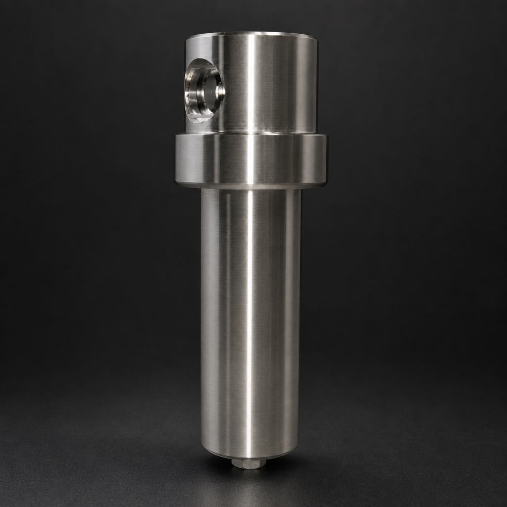
R+F FilterElements bietet die RF-DIL-Reihe von Einweg-Inline-Filtern speziell für diesen Einsatz an. Die RF-DIL-Einheiten sind in Partikel- und Koaleszenzkonfigurationen erhältlich, mit Gehäusen aus 316L-Edelstahl, die für 350 bar ausgelegt sind — geeignet für Hochdruck-Wasserstoffspeicheranwendungen bis 350 bar Betriebsdruck. Ihre kompakte Bauform ermöglicht die Installation in beengten Rohrleitungsabschnitten ohne Bypassventile oder Isolierflansche, und das Einweg-Elementdesign eliminiert das Kontaminationsrisiko bei der Wartung.
Nach dem Speicherbehälterauslass
Ein Koaleszenzfilter am Behälterauslass fängt durch Druckzyklen erzeugte Feuchtigkeitsspitzen ab, bevor sie nachgelagerte Anlagen erreichen. Für Brennstoffzellenanwendungen sollte dieser Filter so ausgelegt sein, dass er bei Betriebsdruck und -durchfluss einen Drucktaupunkt von −60 °C oder besser erreicht. Für Zylinderfullanwendungen gilt die ISO 14687, die −40 °C Drucktaupunkt für Typ-1-Wasserstoff (allgemein industriell) und −60 °C für Typ-2-Wasserstoff (Brennstoffzellenqualität) vorschreibt.
Wenn die nachgelagerte Anwendung besonders empfindlich ist — Analysatorsysteme, Brennstoffzellenstacks oder Halbleiter-Prozessanlagen — empfiehlt R+F FilterElements das RF-H-150 Prozessgasgehäuse mit RF-C Koaleszenzelementen. Das RF-H-150 ist aus 316L-Edelstahl gefertigt, für 100 bar ausgelegt und mit FKM- oder PTFE-Dichtungen für den Einsatz in hochreinen Wasserstoffanwendungen erhältlich. Sein kompaktes Gehäuse (G¼- bis G½-Anschlüsse) macht es geeignet für die Installation in Instrumentenschränken und Analysatorunterkünften, wo der Platz begrenzt ist.
An jeder Verdichterstufe
Ein Partikelfilter unmittelbar vor jedem Verdichtereinlass schützt Ventilsitze und Membranen vor Partikeln, die in der Saugrohrleitungen entstehen. Der Filter sollte für den maximalen Saugvolumenstrom des Verdichters ausgelegt und auf mindestens 5 µm absolut ausgelegt sein — eine feinere Filtration an dieser Stelle birgt das Risiko eines übermäßigen Druckabfalls über den Filter, was zu Kavitation oder vermindertem volumetrischem Wirkungsgrad des Verdichters führen kann.
Filterauswahl: Wesentliche Parameter für den Wasserstoffeinsatz
| Parameter | Vor dem Speicherbehältereinlass | Nach dem Speicherbehälterauslass | Verdichtereinlass |
|---|---|---|---|
| Filtrationsgrad | 1 µm absolut (Partikel) | 0,1 µm absolut (Koaleszenz) | 5 µm absolut (Partikel) |
| Gehäusewerkstoff | 316L Edelstahl | 316L Edelstahl | 316L Edelstahl oder Aluminium |
| Druckstufe | Entsprechend Speicherdruck (bis 350 bar) | Entsprechend Speicherdruck | Entsprechend Saugdruck |
| Dichtungswerkstoff | FKM oder PTFE | FKM oder PTFE | FKM oder NBR |
| Empfohlenes R+F-Produkt | RF-DIL (Einweg-Inline) | RF-H-150 + RF-C-Element | RF-DIL oder RF-H-110-Serie |
| Wechselintervall | 6–12 Monate oder bei Differenzdruckalarm | 12 Monate oder bei Differenzdruckalarm | 6 Monate oder bei Differenzdruckalarm |
Wartungsintervalle und Differenzdrucküberwachung
Der häufigste Wartungsfehler bei Wasserstoff-Filtrationsanlagen ist der Wechsel von Filterelementen nach einem festen Kalenderplan, unabhängig von der tatsächlichen Verunreinigungsbeladung. In einer sauberen, ordnungsgemäß in Betrieb genommenen Anlage können Elemente weit über ihr nominales Wartungsintervall hinaus halten. In einer Anlage mit korrodierenden Rohrleitungen oder einem defekten Verdichter können Elemente innerhalb von Wochen vollständig beladen sein.
Die Differenzdrucküberwachung — ein einfaches Manometer oder ein elektronischer Messumformer, der den Druckabfall über das Filtergehäuse misst — ist der zuverlässigste Indikator für den Elementzustand. R+F FilterElements empfiehlt die Installation eines Differenzdruckanzeigers an jedem Filtergehäuse im Wasserstoffeinsatz, mit einem Alarm bei 0,5 bar Differenzdruck für Koaleszenzelemente und 0,3 bar für Partikelelemente. Wenn der Alarm ausgelöst wird, sollte das Element innerhalb von 24 Stunden gewechselt werden, um einen Bypass-Durchfluss durch das Filtermedium zu verhindern.
Für Anlagen, bei denen ungeplante Wartungsarbeiten besonders störend sind — kontinuierliche Wasserstoffproduktionsanlagen oder Tankstellen mit hoher Auslastung — ermöglichen Duplex-Filteranordnungen mit automatischen Umschaltventilen den Elementwechsel ohne Prozessunterbrechung. R+F FilterElements berät zu Duplex-Konfigurationen für die Prozessgasgehäuse-Reihe und die RF-DIL Inline-Filter-Reihe.
Use our free Engineering Tool to get a filtration recommendation for your specific application in under 2 minutes.
Inbetriebnahme: Das Verunreinigungsfenster
Neue Rohrleitungen und Speicherbehälter stellen während der Inbetriebnahme ein besonderes Verunreinigungsrisiko dar. Schweißspritzer, Flussmittelrückstände und Montageschmierstoffe sind in frisch gefertigten Anlagen vorhanden, und der erste Druckbeaufschlagungszyklus mobilisiert diese Verunreinigungen in den Gasstrom. Es ist in hochreinen Gasanlagen gängige Praxis, temporäre Inbetriebnahmefilter — typischerweise mit 1 µm absolut ausgelegt — an allen kritischen Punkten während der ersten Druckbeaufschlagungs- und Spülsequenz zu installieren und diese nach dem Freispülen der Anlage durch dauerhafte Betriebsfilter zu ersetzen.
R+F FilterElements empfiehlt mindestens drei vollständige Druckbeaufschlagungs- und Entlüftungszyklen, bevor empfindliche nachgelagerte Anlagen angeschlossen werden, mit einer Elementinspektion nach jedem Zyklus. Zeigt das Element nach dem dritten Zyklus sichtbare Verunreinigungen, sollte der Spülvorgang wiederholt werden, bis das Element sauber bleibt.
Konformität und Normen
Die Wasserstoffreinheitsanforderungen für Brennstoffzellenanwendungen sind in ISO 14687:2019 festgelegt, die Höchstkonzentrationen für 14 Verunreinigungsarten vorschreibt, darunter Gesamtpartikel (1 mg/kg), Gesamtkohlenwasserstoffe (2 µmol/mol) und Wasser (5 µmol/mol). Für Wasserstofftankstellen verweist der SAE-J2719-Standard auf ISO 14687 und ergänzt Anforderungen an Probenahme- und Analysehäufigkeit.
Filtrationsanlagen, die in der Europäischen Union im Wasserstoffeinsatz betrieben werden, müssen zudem die Druckgeräterichtlinie (PED 2014/68/EU) für Gehäuse über 0,5 bar Überdruck sowie die ATEX-Richtlinie 2014/34/EU für Anlagen in explosionsgefährdeten Bereichen einhalten. Alle Filtergehäuse von R+F FilterElements der Serien RF-H-110 bis RF-H-170 sowie die RF-DIL-Reihe sind CE-gekennzeichnet und werden mit Konformitätserklärungen geliefert. Wenden Sie sich an R+F FilterElements für ATEX-zertifizierte Konfigurationen und Prüfzertifikate von Drittparteien.
Zusammenfassung: Eine einfache Regel für Wasserstoffreinheit
Die Regel ist einfach: Jede Schnittstelle zwischen dem Elektrolyseur und dem Speicherbehälter ist ein potenzieller Verunreinigungspunkt, und jeder Verunreinigungspunkt benötigt einen Filter. Die Kosten für die Installation und Wartung dieser Filter sind gering im Vergleich zu den Kosten eines verunreinigten Speicherbehälters, eines defekten Verdichters oder eines vergifteten Brennstoffzellenstacks. R+F FilterElements, ein in Deutschland ansässiger Filtrationsspezialist nach europäischen Ingenieurnormen, bietet die RF-DIL Inline-Filter-Reihe und das RF-H-150 Prozessgasgehäuse als zweckentwickelte Lösungen für die Wasserstoffspeicherfiltration an. Beide Produkte sind auf Anfrage mit vollständiger Materialrückverfolgbarkeit, Druckprüfzertifikaten und ATEX-Dokumentation erhältlich.
Für Unterstützung bei der Auslegung von Filtern für Ihr spezifisches Wasserstoffspeichersystem — einschließlich Durchfluss-, Druck- und Reinheitsberechnungen — nutzen Sie den R+F FilterElements Auslegungsassistenten oder wenden Sie sich direkt an das Technikteam.
R+F FilterElements bietet bedarfsortsgenaue Filtrationslösungen, die speziell für die Wasserstoffspeicherung und -verteilung entwickelt wurden — vom Elektrolyseurauslass bis zum Abgabepunkt.
Expertenberatung anfordern →- Selbst Edelstahlrohrleitungen erzeugen Partikelverunreinigungen.
- Ein Speicherbehälter ist kein passives Bauteil.
- Dies ist der kritischste Filtrationspunkt im gesamten System.
- Der häufigste Wartungsfehler bei Wasserstoff-Filtrationsanlagen ist der Wechsel von Filterelementen nach einem festen Kalenderplan, unabhängig von der tatsächlichen Verunreinigungsbeladung.

