Why the Wrong Filter Candle Costs More Than the Right One
In gas filtration, the filter candle — or Filterkerze — is the component that does the actual work. Housings, manifolds, and instrumentation are all secondary to the element itself. Yet in practice, candles are often selected on price alone, without considering construction type, efficiency grade, or compatibility with the process gas. The result is predictable: premature saturation, liquid carry-over into downstream equipment, or a pressure drop that starves the process.
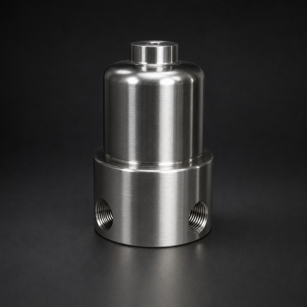
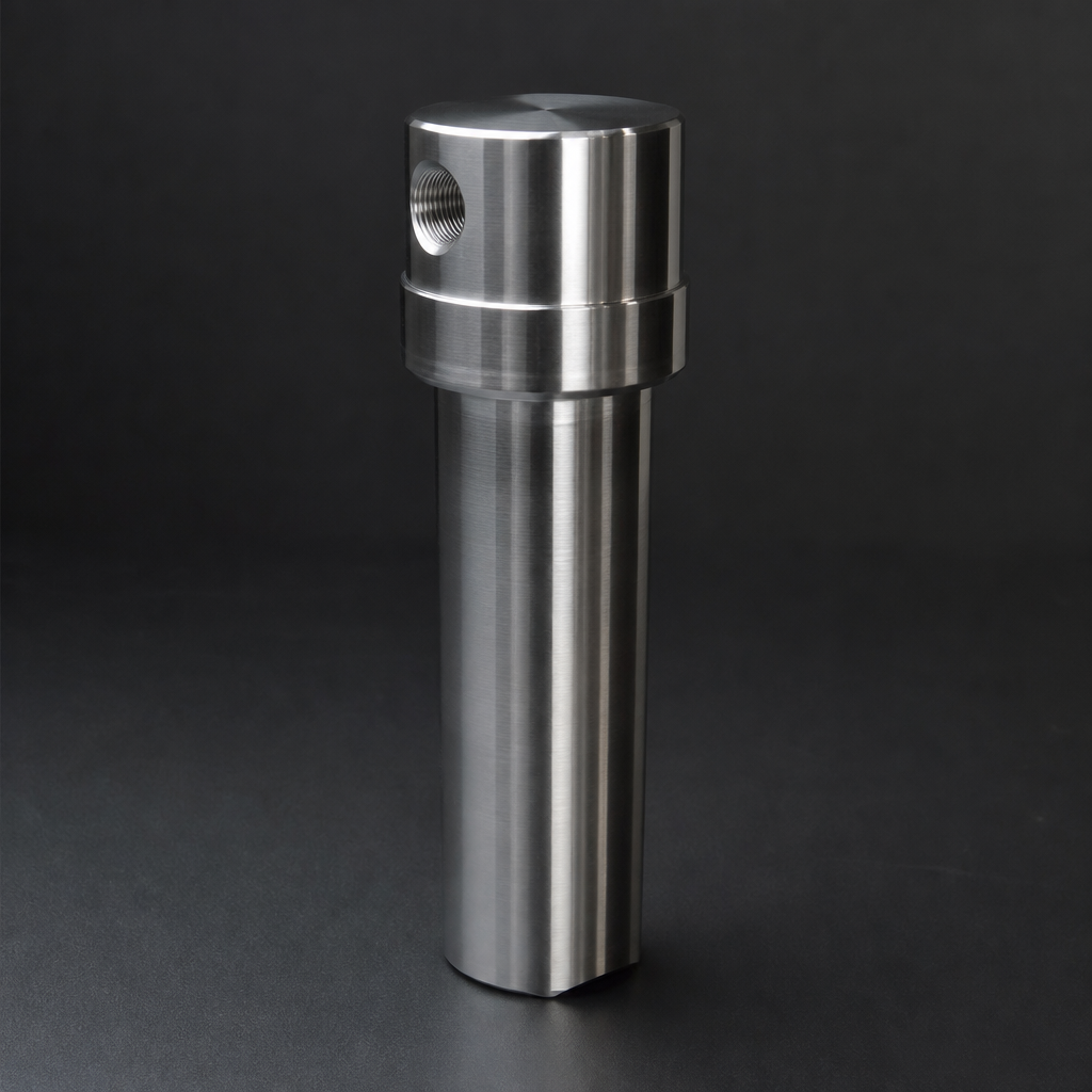
This guide covers everything a process engineer needs to know to specify a filter candle correctly for gas service — from the physics of depth-loading and coalescence to the practical differences between borosilicate microfibre, pleated, sintered metal, and PTFE membrane designs. For housing selection, see the R+F process gas filter range.
Construction Types: Four Designs, Four Different Mechanisms
1. Depth-Loading Borosilicate Microfibre (RF-C Series)
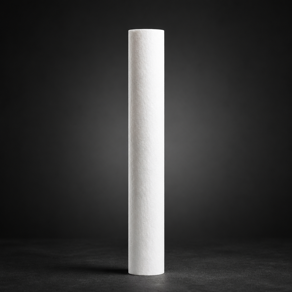
The most widely used candle type in process gas filtration is the depth-loading borosilicate glass microfibre element. The RF-C coalescing element range uses randomly oriented borosilicate fibres with diameters from 0.5 µm to 6 µm, compressed to a controlled density gradient. Gas flows radially inward (outside-in), and particles and liquid aerosols are captured throughout the full depth of the matrix — not just on the surface.
The depth-loading mechanism gives these candles a high dirt-holding capacity relative to their size. More importantly, the tortuous fibre path promotes coalescence: sub-micron liquid droplets collide with fibres, merge into larger droplets, and drain by gravity to the sump. This is why borosilicate microfibre candles are the standard choice for coalescing applications — removing compressor oil aerosols, water mist, and hydrocarbon condensate from natural gas, hydrogen, and instrument air streams.
The RF-C range covers six standard element sizes (12032, 12057, 25064, 25178, 51230, 51476) and is available in efficiency grades from UX (general duty) through HE and XE (high-efficiency coalescing) to AX (activated carbon adsorption layer). Standard temperature rating is 100 °C; S-type elements extend this to 200 °C with a silica binder system.
2. Pleated Particulate Elements (RF-P Series)
Where the duty is purely particulate removal — no liquid aerosols — a pleated element offers a larger filtration area in the same candle envelope. The RF-P particulate element uses a pleated borosilicate or synthetic microfibre medium, achieving 99.99% efficiency at ≥ 0.3 µm. The pleated geometry increases surface area by a factor of 3–5 compared with a depth-loading candle of the same outer diameter, which translates directly into lower initial pressure drop and longer service life in high-dust-load applications.
Pleated elements are not suitable for liquid-laden gas streams: liquid bridging across the pleat channels causes a rapid and irreversible pressure drop increase. If there is any possibility of liquid ingress — condensation, slug flow, or upstream equipment failure — a coalescing RF-C element should be installed upstream.
3. Sintered Metal Candles
For high-temperature service above 200 °C, or where the element must be cleaned and reused, sintered 316L stainless steel or Hastelloy candles are the appropriate choice. Sintered metal elements are rated to 450 °C and can withstand pressure differentials up to 10 bar without structural failure. They are specified for hot gas filtration in chemical reactors, catalyst protection, and high-temperature process streams where polymer or glass-fibre media would degrade.
The trade-off is efficiency: sintered metal candles typically achieve 5–10 µm absolute filtration, which is adequate for catalyst fines and coarse particulate but insufficient for sub-micron aerosol removal. They are also significantly heavier and more expensive than disposable fibre elements.
4. PTFE Membrane Candles
PTFE membrane elements provide absolute filtration at 0.1–1.0 µm with near-zero liquid absorption. They are specified for aggressive chemical service — chlorine, HCl, SO₂, and other corrosive gases — where glass fibre would be attacked, and for applications requiring a true absolute rating rather than a statistical efficiency figure. The RF-GMS-170 membrane separator uses a hydrophobic PTFE membrane to provide an absolute liquid barrier in high-pressure gas lines.
How Coalescence Works in a Candle Geometry
Coalescence is the process by which sub-micron liquid aerosols — too small to be captured by inertial impaction — are collected and merged into drainable droplets. In a cylindrical candle, the mechanism operates in three stages:
- Interception and diffusion: Sub-micron droplets follow gas streamlines but deviate slightly due to Brownian motion, bringing them into contact with fibres. Droplets adhere to the fibre surface by van der Waals forces.
- Coalescence: Droplets on adjacent fibres merge. As the merged droplet grows, surface tension is overcome and it migrates along the fibre to a node point.
- Drainage: Droplets at node points grow until gravity exceeds surface tension, then fall to the housing sump. The sump must be drained regularly — either manually or via an automatic float drain — to prevent re-entrainment.
The outside-in flow direction in a coalescing candle is critical: it ensures that coalesced liquid drains downward on the outer surface of the element, away from the clean gas outlet. Inside-out flow would carry coalesced liquid into the clean gas stream.
Efficiency Grades Explained
R+F FilterElements uses a standardised efficiency grade system for the RF-C and RF-P ranges, aligned with ISO 8573-1 oil and particle classes:
The grade codes map to ISO 8573-1 classes as follows: UX (general particulate, ISO Class 3–4), UR (fine particulate, ISO Class 2), UE (sub-micron particulate, ISO Class 1), ST (standard coalescing, ISO Class 2 oil), ME (medium-efficiency coalescing), HE (high-efficiency coalescing, ISO Class 1 oil), XE (extra-high-efficiency coalescing, ISO Class 1 oil < 0.01 mg/m³), AX (activated carbon adsorption, ISO Class 1 oil vapour). For most process gas applications, HE or XE grade coalescing elements are specified.
Need help selecting the right filter candle?
Depth-Loading vs Pleated: A Direct Comparison
| Parameter | Depth-Loading (RF-C) | Pleated (RF-P) |
|---|---|---|
| Filtration mechanism | Depth (interception + diffusion) | Surface (sieving + interception) |
| Liquid aerosol removal | Yes — coalescing | No — not suitable |
| Dirt-holding capacity | High | Very high (large surface area) |
| Initial pressure drop | Low–medium | Very low |
| Efficiency at 0.1 µm | 99.99% (HE/XE grade) | 99.99% at ≥ 0.3 µm |
| Max. temperature | 100 °C (200 °C S-type) | 100 °C |
| Typical application | Coalescing, process gas, H₂, N₂ | Dry gas, instrument air, dust |
Use our free Engineering Tool to get a filtration recommendation for your specific application in under 2 minutes.
Selection Matrix by Application
The following matrix summarises the recommended candle type for common process gas applications. For detailed sizing — including flow rate, pressure drop, and element quantity — use the R+F Engineering Sizing Tool.
Natural Gas and Biogas
Natural gas and biogas streams typically carry compressor oil aerosols, water condensate, and hydrocarbon liquids. The standard specification is an RF-C HE or XE coalescing element in an RF-H-150 or RF-H-160 process gas housing, with an automatic float drain. Where H₂S is present, K-type elements with FKM seals are required.
Hydrogen (Electrolysis and Reforming)
Hydrogen from electrolysis carries KOH mist (alkaline electrolysis) or water vapour (PEM). KOH mist is highly corrosive and requires XE-grade coalescing elements with PTFE or FKM seals. For PEM hydrogen, HE-grade elements are typically sufficient. See the R+F hydrogen filtration solutions page for full system configurations.
Instrument and Analyser Gas
Sample conditioning and analyser protection require the highest efficiency grades and the lowest possible contamination risk. RF-C XE elements in RF-H-110 to RF-H-170 stainless steel housings are the standard specification. For ultra-pure or semiconductor applications, SilcoNert-coated housings eliminate adsorption of trace components.
Vacuum Pump Exhaust
Vacuum pump exhaust filtration uses RF-CS silica-bonded elements rated to 200 °C, installed in RF-H-420 to RF-H-456 exhaust filter housings. The high oil carry-over from vacuum pumps demands HE or XE grade elements with large sump capacity.
End-Cap and Adapter Configurations
Filter candles are available with a range of end-cap configurations to suit different housing designs. The most common are:
- Flat closed / flat open: Standard configuration for RF-H-310 to RF-H-395 compressed air housings. The open end seats on an O-ring in the housing bowl.
- 222 / 226 bayonet: Sanitary and pharmaceutical standard, used in stainless steel housings for food-grade gas applications.
- Threaded adapters: Used in RF-H-110 to RF-H-170 instrumentation housings for high-pressure service up to 700 bar.
- Fin / DOE (double open end): Used in multi-element housings where the element is retained by a central tie rod.
Always verify end-cap compatibility before ordering replacement elements. The RF-C and RF-P element part numbers encode the end-cap configuration in the suffix — contact R+F FilterElements if you are unsure which suffix applies to your housing.
- The most widely used candle type in process gas filtration is the depth-loading borosilicate glass microfibre element.
- Interception and diffusion:
- R+F FilterElements uses a standardised efficiency grade system for the RF-C and RF-P ranges, aligned with ISO 8573-1 oil and particle classes:
- The following matrix summarises the recommended candle type for common process gas applications.
Related Reading
- Coalescing vs Particulate Filter Elements — When to Use Which
- ISO 8573-1 Compressed Air Quality Classes Explained
- Hydrogen Electrolysis Filtration — KOH Mist and Water Vapour Removal
Try our Engineering Sizing Tool → or discuss your requirements with our team.