
Analyser Sample Conditioning Train
From the process tap to the analyser inlet: where particles, aerosol and liquid slugs enter a sample system, which filter stage belongs where, and how to keep lag time short and the analyser dry.
The sample system, stage by stage
Click a stage to see what happens to the sample and which R+F components fit.
3. Coalescing filter
Removes fine aerosol and droplets and drains them.
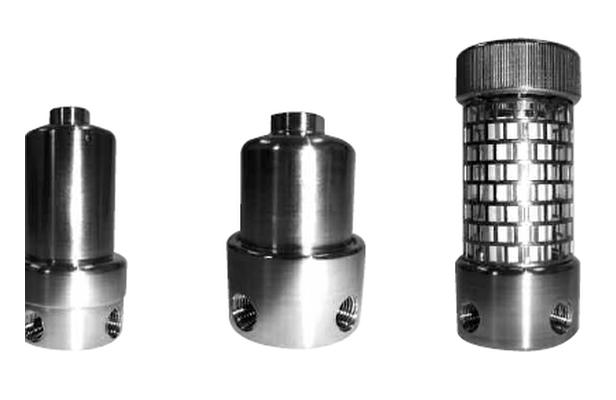
- RF-H-122: stainless steel, ¼″ NPT, ¼″ drain, 340 bar, 200 °C. RF-H-120 is the ⅛″ NPT version with the same 12 × 57 mm element.
- RF-C-12057-HE: borosilicate glass microfibre, 99.99 % @ 0.01 µm, −50 to +150 °C. Flow from inside to outside: droplets merge, run down the outside of the element and leave through the drain.
- Heated sample lines: RF-CS-12057-HE (silica-bonded) up to 500 °C — the housing limit of 200 °C for stainless steel and the seal limit always apply.
- Coalescing elements are not cleanable: change every 3 months, or earlier when the differential pressure rises.
Why this order works
Each stage protects the next one. Swap the order and the fine stages take loads they were not designed for.
Bulk before fine
Particles and bulk liquid first, aerosol second, the absolute membrane barrier last. A fine stage at the front overloads within days.
Fast loop for lag time
The bypass keeps the sample fresh. Filter volume and dead volume in the analyser branch add lag time — keep them small.
Temperature decides the element
Above the dew point the sample stays a gas. In heated lines choose silica-bonded elements and check the housing and seal limits.
Drains must work
A coalescer only protects if the separated liquid can leave. Use housings with drain wherever liquid can occur.
Unheated vs heated sample line
The same 12 × 57 mm element format, different materials depending on sample temperature.
| Unheated sample line | Heated sample line | |
|---|---|---|
| Coalescing element | RF-C-12057-HE, −50 to +150 °C | RF-CS-12057-HE (silica-bonded), up to 500 °C |
| Efficiency | 99.99 % @ 0.01 µm | 99.99 % @ 0.01 µm |
| Housing | RF-H-122 / RF-H-120, 340 bar, 200 °C | RF-H-122 / RF-H-120 (200 °C limit) or heatable RF-HH-122ST |
| Membrane separator | RF-M-GMS170 (max. 100 °C) | Only after cooling below 100 °C |
| Element change | Every 3 months or at rising ΔP | Every 3 months or at rising ΔP |
Housing and seal limits always apply. Final configuration on request with your sample pressure, temperature, flow and composition.
Questions from analyser engineers
No. Grade codes are manufacturer-specific. Compare efficiency in percent, the particle size it refers to and the test method. All R+F borosilicate microfibre grades are stated at 0.01 µm.
What we need for a configuration
With these data we propose a complete sample-conditioning filter set.
- Sample medium and composition (including condensable components)
- Pressure at the tap and at the analyser inlet
- Sample temperature, heated or unheated line
- Analyser flow and fast-loop flow
- Expected contaminants: particles, aerosol, liquid slugs
- Connection size (NPT) and number of analysers
Planning or servicing a sample system?
Send us your sample data or the element dimensions of your existing system. We propose the matching filter stages — housings with NPT connections and elements in 12 × 57 mm format.